
A hot plate mold for lamp manufacturing

A mold and hot plate technology, applied in the field of hot plate molds, to achieve the effect of easy replacement, avoiding manpower, and facilitating replacement work

Active Publication Date: 2021-05-28
湖南德霸照明制造有限公司
View PDF8 Cites 0 Cited by
  • Summary
  • Abstract
  • Description
  • Claims
  • Application Information

AI Technical Summary

Problems solved by technology

[0005] Aiming at the deficiencies of the prior art, the present invention provides a hot plate mold for the manufacture of lamps, mainly to solve problems such as the replacement of the lower mold

Method used


Image

  • A hot plate mold for lamp manufacturing
  • A hot plate mold for lamp manufacturing
  • A hot plate mold for lamp manufacturing

Examples


Embodiment 1

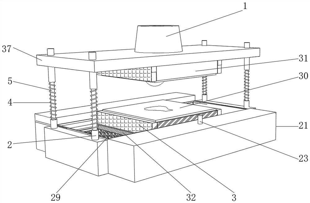
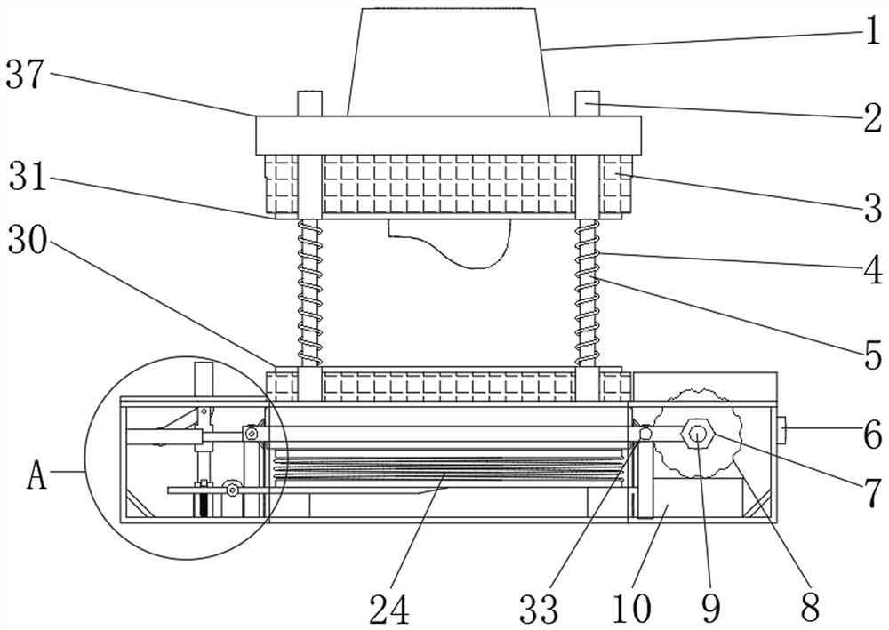
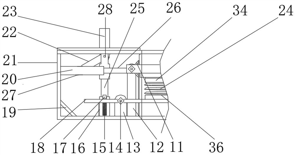
[0032] refer to Figure 1-6 , a hot plate mold for the manufacture of lamps, including a housing 21, the upper surface of the housing 21 has an installation opening, and the upper surface of the installation opening is fixed with a sliding rail 29 by bolts, and the inner four walls of the housing 21 are welded with support Frame 19, both sides of the inner wall of sliding rail 29 are all fixed with heat insulation boards by bolts, and the bottom of the inner wall of housing 21 is fixed with support plate 10 by bolts, and the upper surface of support plate 10 is fixed with motor 8 by bolts, and the two sides of the upper surface of housing 21 The first support column 2 is welded on both sides, the first support column 2 is plugged with the first slide bar 5, and one end of the first slide bar 5 is plugged with the second support column, and one side of the outer wall of the second support column is welded There is the same top plate 37, the upper surface of the top plate 37 is ...

Embodiment 2

[0036]refer to Figure 7 , a hot plate mold for the manufacture of lamps, including a top plate 3, both sides of the bottom of the top plate 37 are fixed with a lampshade 38 by bolts, and one end of the inner wall of the lampshade 38 is threadedly connected with an energy-saving lamp 39, through the setting of the energy-saving lamp 39 can be installed Watch the production situation more clearly when working, and be more careful when repairing or replacing equipment. There are multiple hinges fixed on the four sides of the upper surface of the housing 21 by bolts, and a transparent protective plate 35 is fixed on one end of the hinge by bolts. The setting of the transparent protection 35 can avoid the danger of parts splashing out when the machine is working, and at the same time, the operating condition of the equipment can be observed.

[0037] The working principle of this embodiment: when in use, when the mold is running at night or when parts are replaced and maintained, ...


PUM


Abstract

The invention relates to the technical field of mold processing, and discloses a hot plate mold used for manufacturing lamps, which includes a housing, an installation opening is opened on the upper surface of the housing, and a slide rail is fixed on the upper surface of the installation opening through bolts. The housing The four walls inside the body are welded with a support frame, both sides of the inner wall of the sliding rail are fixed with heat shields by bolts, the bottom of the inner wall of the housing is fixed with a support plate by bolts, and the upper surface of the support plate is fixed with a motor by bolts, Both sides of the upper surface of the housing are welded with first support columns, one end of the first support column is plugged with a first slide rod, and one end of the first slide rod is plugged with a second support column. The present invention can drive the movement bar to move backward when the switch is pressed down, and pull the slide plate fixed on the lower mold backward, so that the lower mold can be moved, and the lever plate can be moved by the first slide bar when the second slide bar moves downward. Supported by the runner, the bar plate is tilted up to push the lower mold upwards, which is easier to replace.

Description

technical field [0001] The invention relates to the technical field of mold processing, in particular to a hot plate mold used for manufacturing lamps. Background technique [0002] As we all know, the hot plate mold used for lamp manufacturing is a kind of machinery used to quickly manufacture lamp parts, which has been widely used in the field; the existing hot plate mold for lamp manufacturing includes molds for processing metal and processing Non-metallic and powder metallurgy molds; the existing hot plate molds for lamps and lanterns are used to find that the lower mold is easy to be damaged due to excessive heat, and it is inconvenient to replace it many times, which affects work efficiency. [0003] After retrieval, the authorized publication number is CN109630931A patent, which discloses a composite lamp mold, including an upper mold and a lower mold adapted to the upper mold, a base is provided in the upper mold, and the lower mold The outer jacket is provided with...

Claims


Application Information

Patent Timeline
Patent Type & Authority Patents(China)
IPC IPC(8): B29C45/26
CPCB30B15/02B30B15/026B30B15/028
Inventor 陆卫黄陆文辉张冬
Owner 湖南德霸照明制造有限公司
Learn More