Movable mounting device and method for landing chassis
A technology for mounting devices and landing gear, which is applied in the field of mobile mounting devices for landing gear, can solve problems such as time-consuming and labor-intensive, and achieve the effects of reducing labor intensity, reliable clamping, and convenient installation
- Summary
- Abstract
- Description
- Claims
- Application Information
AI Technical Summary
Problems solved by technology
Method used
Image

Examples
Embodiment Construction
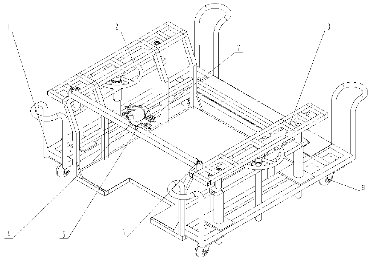
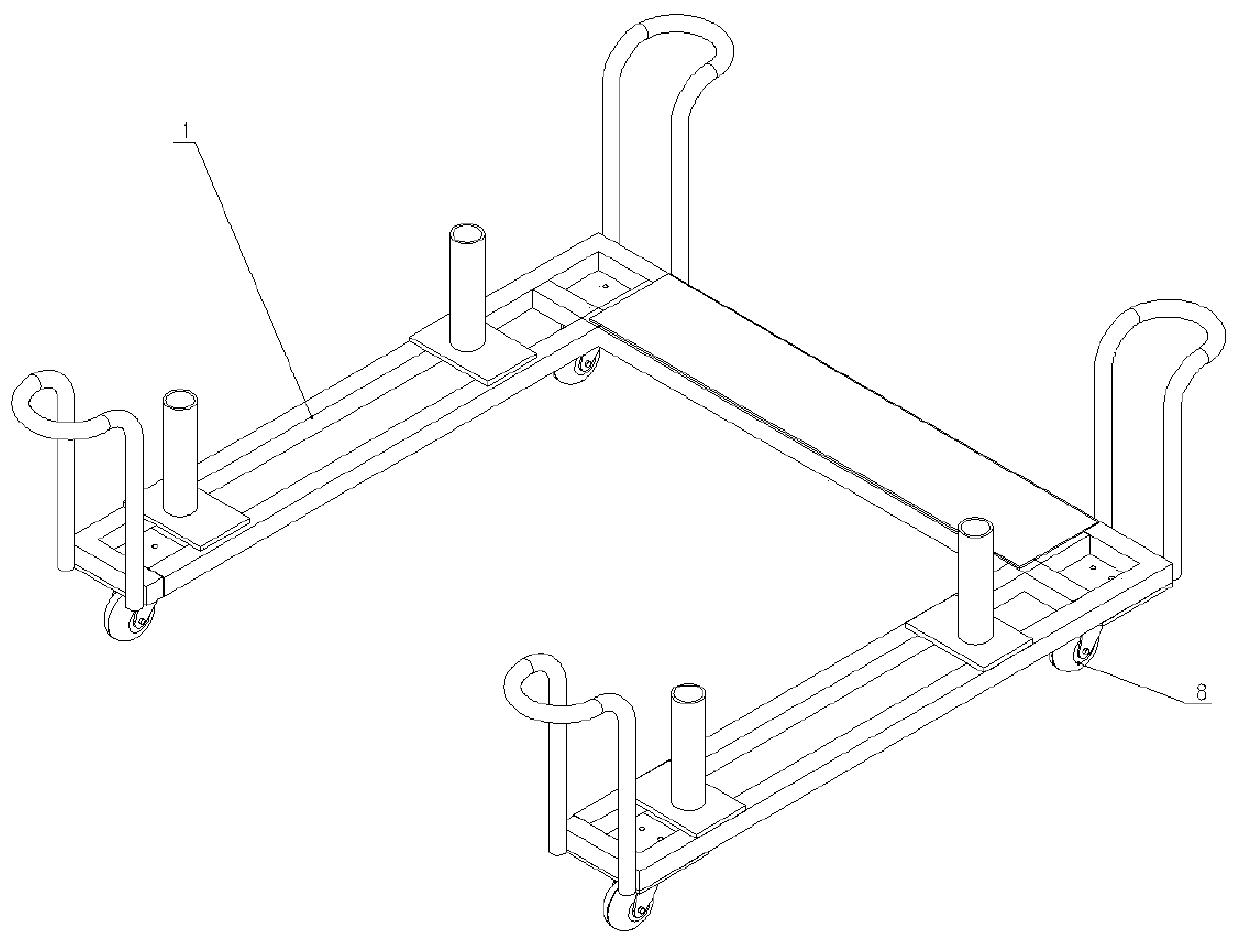
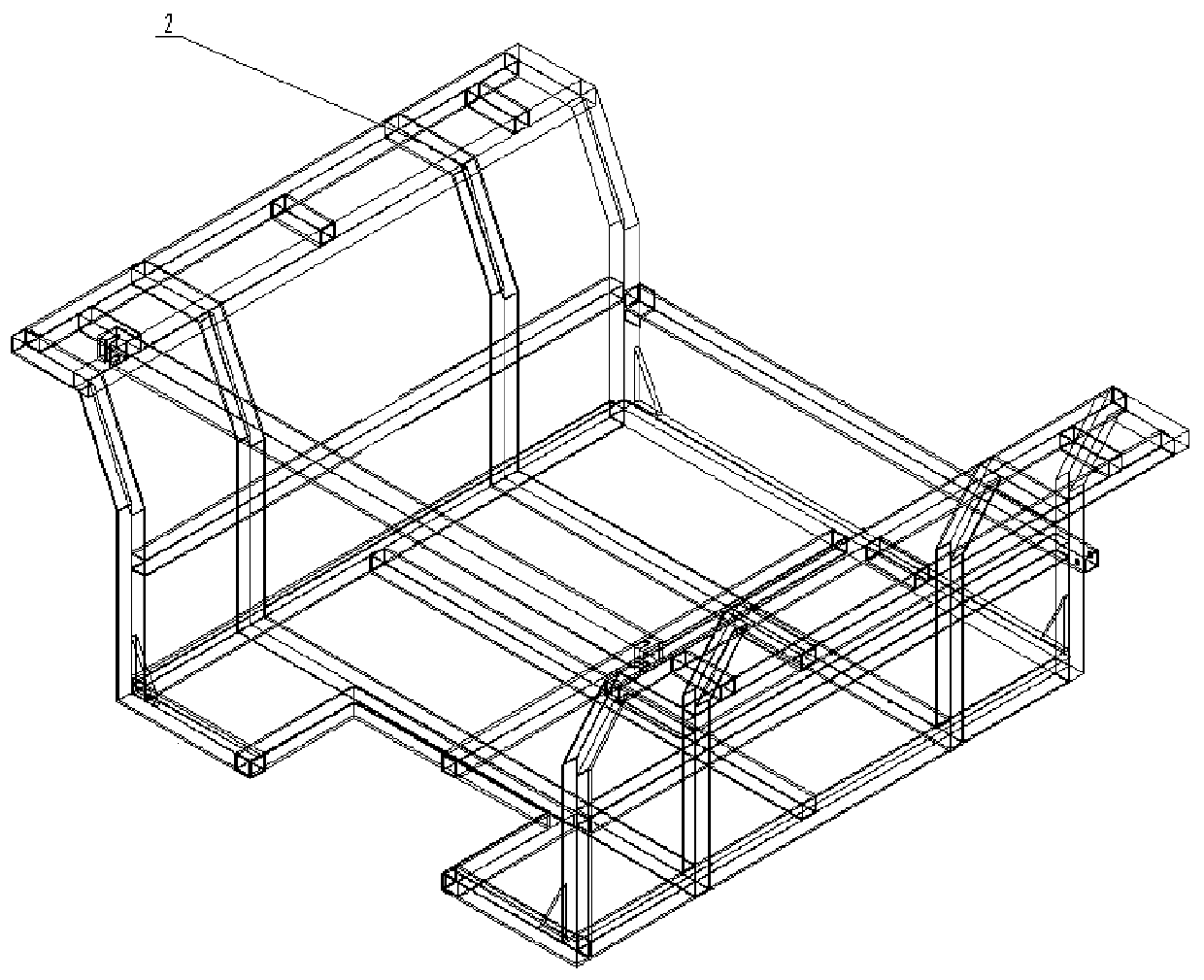
[0025] The specific implementation manners of the present invention will be further described in detail below. see figure 1 , figure 2 , image 3 , Figure 4 with Figure 5 , the present invention provides a landing gear mobile installation device, including a vehicle frame 1, a moving bracket 2, a lifting mechanism 3, a lower splint set 4, an upper splint 5, a locking bolt assembly 6, a fixing bolt assembly 7, and a movable wheel 8; The bottom of the vehicle frame 1 is a U-shaped frame, with handles at the four corners of the frame, four guide pipes at the middle of both sides, the bottom of the frame is welded to the bottom plate, and movable wheels 8 are fixed by bolts; Recessed structure, the moving bracket 2 is connected with the lifting mechanism 3, the upper end surface of the lifting mechanism 3 is connected with the moving bracket 2, and a threaded pair consisting of a screw, a nut and a hand wheel is arranged in the middle, and guide sliders are used on both sid...
PUM
 Abstract
Description
Claims
Application Information
 - Generate Ideas
- Intellectual Property
- Life Sciences
- Materials
- Tech Scout
- Unparalleled Data Quality
- Higher Quality Content
- 60% Fewer Hallucinations
Browse by: Latest US Patents, China's latest patents, Technical Efficacy Thesaurus, Application Domain, Technology Topic, Popular Technical Reports.
© 2025 PatSnap. All rights reserved.Legal|Privacy policy|Modern Slavery Act Transparency Statement|Sitemap|About US| Contact US: help@patsnap.com