
Microfluidic system for digital polymerase chain reaction of a biological sample, and respective method

A technology of microfluidic systems and biological samples, applied in the field of reaction sites, can solve the problems of insufficient generation of reproducible test results, expensive and other problems, and achieve the effect of improved microfluidic systems and avoid negative effects

Pending Publication Date: 2020-02-25
F HOFFMANN LA ROCHE & CO AG
View PDF3 Cites 4 Cited by
  • Summary
  • Abstract
  • Description
  • Claims
  • Application Information

AI Technical Summary

Problems solved by technology

In particular, the solutions already proposed in the prior art (see above) are either too expensive or insufficient to generate reproducible test results

Method used


Image

  • Microfluidic system for digital polymerase chain reaction of a biological sample, and respective method
  • Microfluidic system for digital polymerase chain reaction of a biological sample, and respective method
  • Microfluidic system for digital polymerase chain reaction of a biological sample, and respective method

Examples


Embodiment Construction

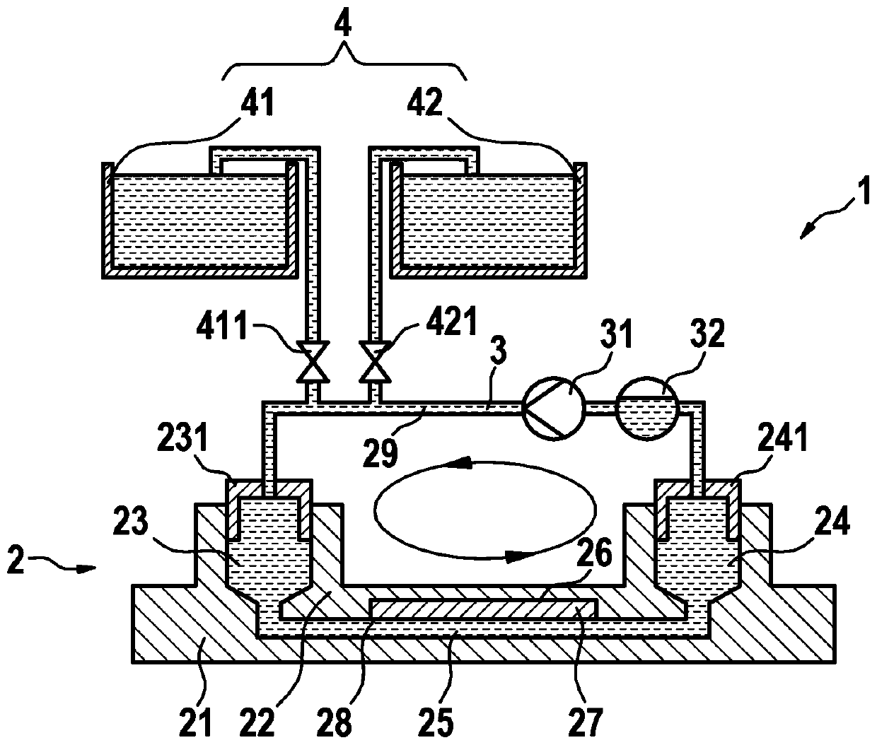
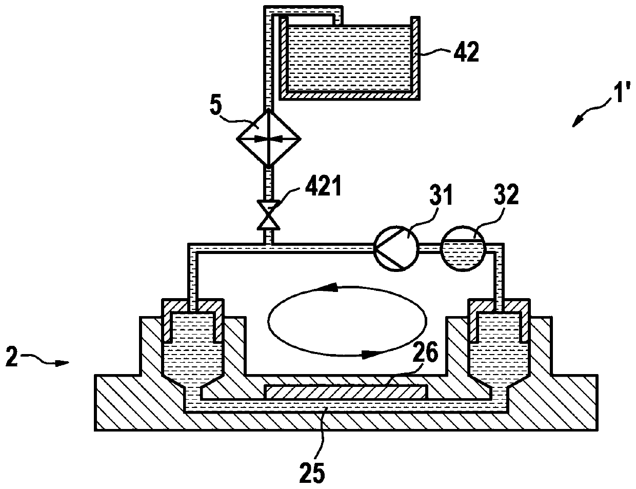
[0096] figure 1 A microfluidic system 1 for dPCR of a biological sample according to a first embodiment of the invention is shown in a schematic representation, wherein the main components are provided in illustrative sections or as icons. Such as figure 1 The illustrated microfluidic system 1 comprises a microfluidic device 2 in the form of a microfluidic chip, the device 2 shown with Figure 3B A similar structure to the prior art chip 7 depicted in , where the device 2 essentially consists of a lower plate 21 and an upper plate 22 and provides an inlet 23 , an outlet 24 , and a flow channel 25 connecting the inlet 23 to the outlet 24 . Furthermore, on the upper side within the flow channel 25 (ie on the inner side of the upper plate 22 ) a reaction zone array 26 in the form of microwells or nanowells is provided, so that the reactions in the reaction zones 26 can be monitored from above. Furthermore, in the state shown, the microfluidic device 2 has been flushed with th...


PUM


Abstract

The application provides a microfluidic system for digital polymerase chain reaction (Dpcr) of a biological sample, and a respective method.

Description

technical field [0001] In general, the present invention relates to the technical field of sample analysis, such as the determination of chemical reactions or biochemical reactions, and more particularly to the technical field of high-throughput analysis of biological samples. In more detail, the present invention relates to a microfluidic system for digital polymerase chain reaction (dPCR) of biological samples. In further detail, such a system comprises a microfluidic device having flow channels in fluid communication with an array of reaction regions (often also referred to as partitions implemented as reaction chambers or reaction vessels), for example in the form of wells or microwells , the reaction area respectively acts as a reaction site for a chemical reaction or a biological reaction of at least one biological sample provided therein, and the system can achieve the desired in a microfluidic device as fast and as reliably as possible. Thermal cycle temperature distr...

Claims


Application Information

Patent Timeline
Patent Type & Authority Applications(China)
IPC IPC(8): C12M1/38C12M1/02C12M1/00
CPCB01L7/525B01L3/502723B01L3/5027B01L2200/0684B01L2200/0689B01L2300/048B01L2300/0861B01L3/502715B01L3/502769B01L7/52B01L2300/0654B01L2300/185B01L2400/0487B01J2219/00722B01L3/508B01L2200/027B01L2300/0627
Inventor C·斯坦纳特M·齐德
Owner F HOFFMANN LA ROCHE & CO AG
Learn More