Control valve arc extinguishing device for thermal power plant
A thermal power plant, arc extinguishing device technology, applied in the direction of circuits, electric switches, electrical components, etc., can solve the problems of shortening the service life of contacts, reducing the service life of control valves, and overvoltage breakdown, so as to improve the suppression of arcing The effect of increasing the service life and the effect of suppressing arcing
- Summary
- Abstract
- Description
- Claims
- Application Information
AI Technical Summary
Problems solved by technology
Method used
Image

Examples
Embodiment 1
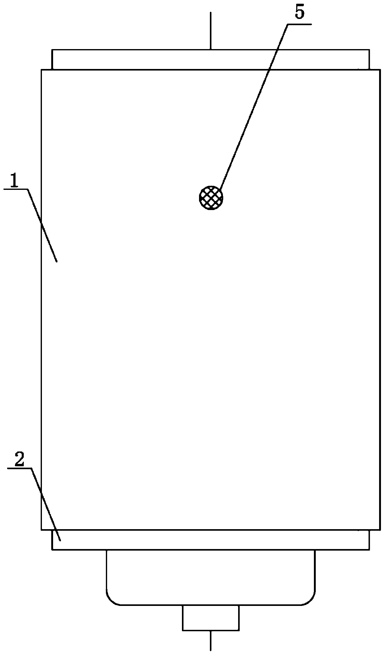
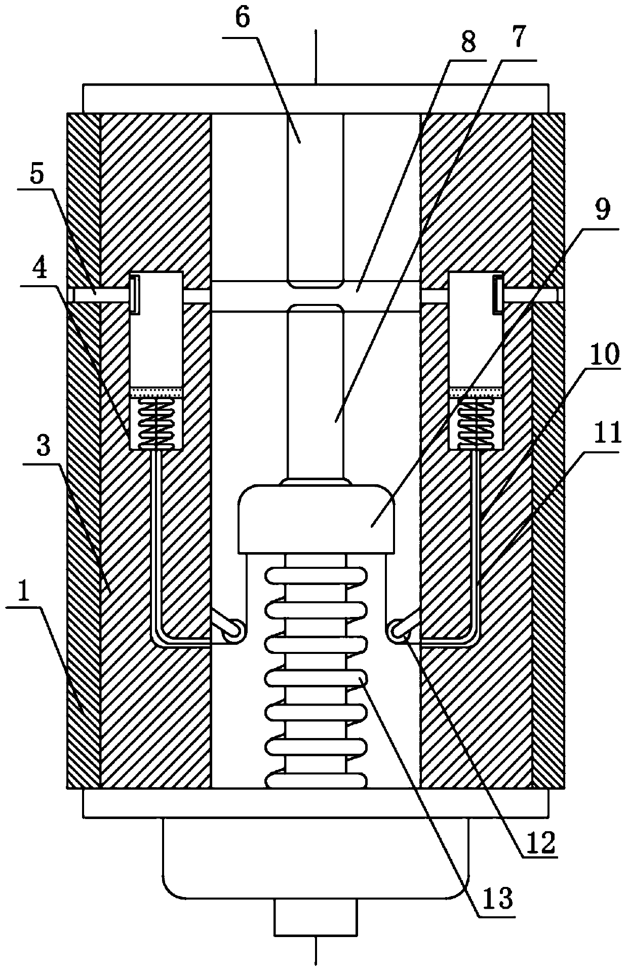
[0034] see Figure 1-5 , the present invention provides a technical solution: a control valve arc extinguishing device for a thermal power plant, comprising: a housing 1, a static end conductive block 2, a blower mechanism 4, a static end conductive rod 6, a dynamic conductive rod 7 and a connecting seat 9.
[0035] Wherein, the housing 1 is specifically made of ceramic material.
[0036] Further, the overall shape of the housing 1 is a cylindrical structure.
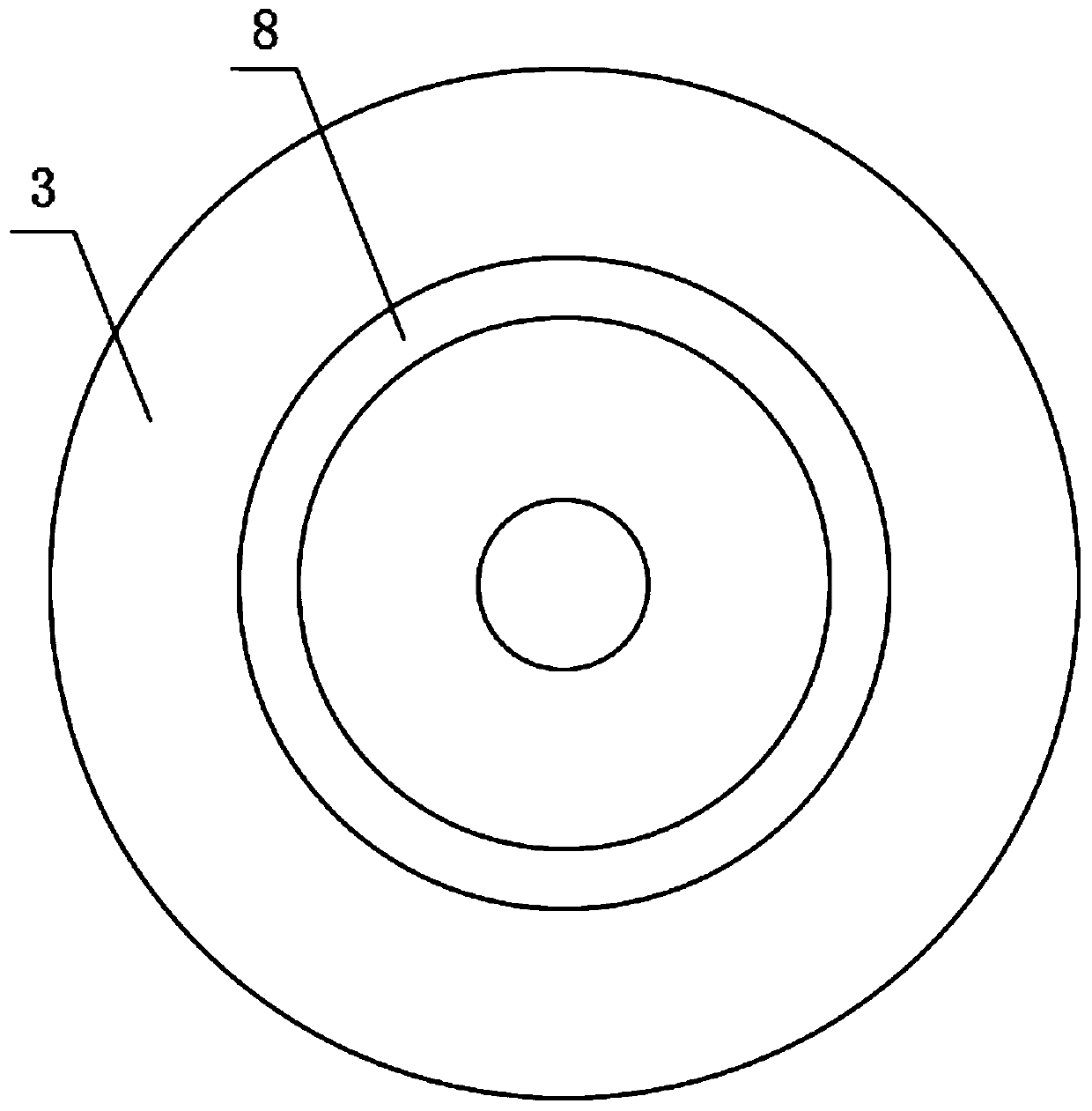
[0037] Wherein, the blowing mechanism 4 includes a sleeve 3 and a cylinder 15, the sleeve 3 is provided with a cylinder 15 and a wire hole 10 around the inside, and the wire hole 10 is fixedly connected to the bottom end of the cylinder 15, and the cylinder 15 No. 2 spring 21 is fixedly installed at the inner bottom of 15, and a piston 20 is fixedly installed at the upper end of said No. 2 spring 21, and the piston 20 is slidingly connected with the cylinder 15. The inner wall surface of the sleeve 3 is fixedly instal...
PUM
 Abstract
Description
Claims
Application Information