
Plug-in cable joint for temporary laying

A cable connector, plug-in technology, applied in the power grid field, can solve the problems of low work efficiency and long recovery time, and achieve the effect of not easy to disconnect easily

Active Publication Date: 2020-02-25
EXAMING & EXPERIMENTAL CENT OF ULTRAHIGH VOLTAGE POWER TRANSMISSION COMPANY CHINA SOUTHEN POWER GRID
View PDF7 Cites 3 Cited by
  • Summary
  • Abstract
  • Description
  • Claims
  • Application Information

AI Technical Summary

Problems solved by technology

[0005] In view of the above problems, the present invention proposes a plug-in cable joint for temporary laying, which mainly solves the problems of long recovery time and low work efficiency of existing connectors during temporary laying

Method used


Image

  • Plug-in cable joint for temporary laying
  • Plug-in cable joint for temporary laying
  • Plug-in cable joint for temporary laying

Examples


Embodiment Construction

[0016] In order to deepen the understanding of the present invention, the present invention will be further described below in conjunction with the examples, which are only used to explain the present invention, and do not constitute a limitation to the protection scope of the present invention.

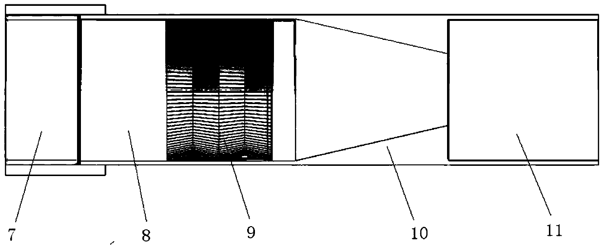
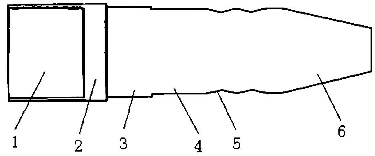
[0017] according to Figure 1 to Figure 3 As shown, this embodiment proposes a plug-in cable joint for temporary laying, including a male plug and a female plug that cooperate with each other; one end of the male plug is sequentially provided with a first copper nose 1 and a limit ring segment 2 , external thread ring 3, internal transition ring 4, contact finger groove 5, tapered plug 6, the tapered male plug facilitates quick alignment with the female plug; one end of the female plug is sequentially provided with a nut 7, an external transition ring 8 , W-shaped shrapnel metal contact fingers 9, tapered socket 10 and second copper nose 11, the nut 7 can slide on the outer transitio...


PUM


Abstract

The invention discloses a plug-in cable joint for temporary laying. The plug-in cable joint comprises a male plug and a female plug which are matched with each other; one end of the male plug is sequentially provided with a first copper nose, a limiting ring section, an outer thread ring, an inner transition ring, a contact finger groove and a conical plug; a nut, an outer transition ring, an elastic sheet metal contact finger, a conical socket and a second copper nose are sequentially arranged at one end of the female plug; the nut can slide on the outer transition ring of the female plug; and the nut is in threaded connection with the outer threaded ring of the male plug. According to the invention, the male plug and the female plug are respectively installed on two cables; in use, the male plug of one cable is inserted into the female plug of the other cable; and finally the nut and the outer thread ring are rotated to perform threaded connection to lock the two cables, so that theconnected cables can be in full contact with each other, have mechanical capacity and are not easy to break, the recovery time during temporary laying is shortened, and the working efficiency is improved.

Description

technical field [0001] The invention relates to the technical field of power grids, in particular to a plug-in cable joint for temporary laying. Background technique [0002] In order to ensure that the cables can meet the flow requirements after being connected, the existing cable core wires usually adopt the following connection methods: copper tube crimping, welding, bolt connection, and terminal crimping. [0003] Crimping, use hydraulic pliers to crimp the copper nose or connecting tube and the conductive core wire of the cable together. This method has good contact, and is convenient in construction and suitable for long-term use, but it also has certain shortcomings. When it is necessary to temporarily lay extended cables, after the cables are used, the core wires at the joints need to be cut short to connect the cables. Recycle. Welding methods include soldering, copper-aluminum welding, etc., but for temporarily laid cables, the welding method also has the problem...

Claims


Application Information

Patent Timeline
Patent Type & Authority Applications(China)
IPC IPC(8): H01R13/40H01R13/502H01R13/52H01R13/622H01R13/627H01R13/629H01R24/38
CPCH01R13/40H01R13/502H01R13/52H01R13/5202H01R13/622H01R13/627H01R13/629H01R24/38
Inventor 夏辉张建刚邬乾晋吴德贯李红元潘凯邵成林龙方宇许毅杨栋金辉王鑫肖黄能孙琨丁洋杨成
Owner EXAMING & EXPERIMENTAL CENT OF ULTRAHIGH VOLTAGE POWER TRANSMISSION COMPANY CHINA SOUTHEN POWER GRID
Learn More