Hybrid excitation wound rotor and hybrid excitation wound synchronous motor

A hybrid excitation and winding rotor technology, applied to synchronous motors with stationary armatures and rotating magnets, synchronous machines, synchronous machine parts, etc., can solve the problem that the torque component cannot be fully utilized, and achieve improved torque Effects of output, improved torque density, and improved performance

Pending Publication Date: 2020-02-25
SHANDONG UNIV
View PDF3 Cites 4 Cited by
  • Summary
  • Abstract
  • Description
  • Claims
  • Application Information

AI Technical Summary

Problems solved by technology

The design of the traditional hybrid excitation wound synchronous motor is based on the rotor structure of symmetrical permanent magnets and field windings, which also makes the motor unable to make full use of the torque components

Method used


Image

  • Hybrid excitation wound rotor and hybrid excitation wound synchronous motor
  • Hybrid excitation wound rotor and hybrid excitation wound synchronous motor
  • Hybrid excitation wound rotor and hybrid excitation wound synchronous motor

Examples


Embodiment 1

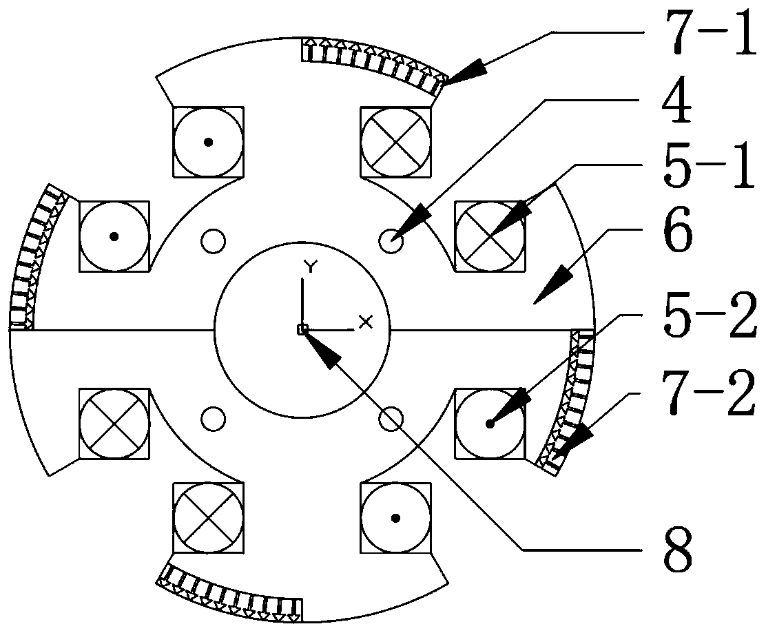
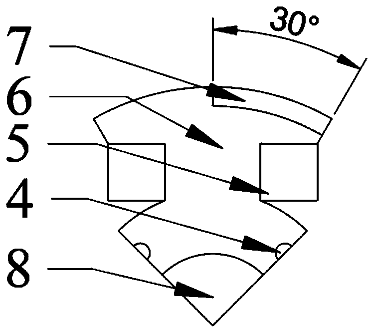
[0031] In one or more embodiments, a hybrid excitation wound rotor is disclosed, which is applied to a wound permanent magnet motor. The rotor includes a rotating shaft 8, a rotor core 6 fixed on the rotating shaft 8, and a rotor core 6 on the rotor core 6. Winding coils, and permanent magnets 7 installed at the ends of the salient poles of the rotor. A set of winding coils is installed on each salient pole to generate rotor magnetomotive force. A piece of tile-shaped permanent magnet 7 is installed along the opposite side of the rotation direction of the motor rotor on the geometric center line of each salient pole end, and the permanent magnet 7 makes the rotor asymmetric. The iron core of the rotor part is formed by axially laminating cold-rolled silicon steel sheets. The winding on the rotor core 6 is connected to the DC power supply through the brush slip ring, and the current passes through the winding to generate the rotor magnetomotive force.

[0032] The motor part ...

Embodiment 2

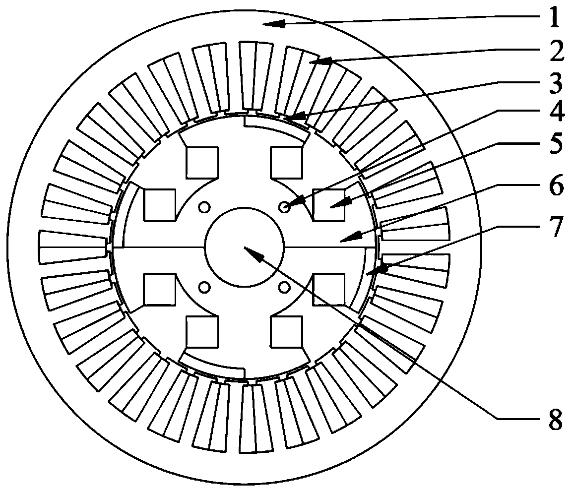
[0040]In one or more embodiments, a hybrid excitation wound synchronous motor is disclosed, referring to figure 1 , The high-performance hybrid excitation wound synchronous motor has a stator part and a rotor part inside the casing.

[0041] Wherein, the rotor part adopts the rotor part structure disclosed in the first embodiment.

[0042] The stator part includes: stator core 1 and stator winding 2. The stator core 1 is formed by laminating silicon steel sheets in the direction of the rotating shaft 8. The silicon steel sheets are thin plates made by adding silicon to iron to reduce eddy current loss. The stator core 1 is cylindrical and extends in the direction of the rotating shaft 8 of the rotating shaft 8 . The stator slots are arranged at equal intervals along the circumferential direction on the inner periphery of the stator, and extend from the stator core 1 side to the rotating shaft 8 in a convex shape. In this embodiment, 27 stator slots are provided, and three-p...


PUM


Abstract

The invention discloses a hybrid excitation wound rotor and a hybrid excitation wound synchronous motor. The hybrid excitation wound rotor comprises a rotating shaft positioned in the center of the rotor; a rotor core is arranged outside the rotating shaft; a set number of salient poles are arranged on the rotor core; coils are wound on two sides of each salient pole to form a rotor exciting winding; permanent magnets are mounted on the surface of one side, opposite to the rotating direction of the motor rotor, of the geometric center line of each salient pole; and the permanent magnets of thewhole rotor are asymmetrically distributed. According to the hybrid excitation wound rotor, the direct-current excitation torque and the permanent magnet torque can be effectively utilized; the asymmetric design of the permanent magnets not only increases the salient pole ratio of the motor, but also increases the reluctance torque; and the direct-current excitation torque, the permanent magnet torque and the reluctance torque of the motor are superposed at the same or similar current phase angle to improve the electromagnetic torque, so that the torque density, the efficiency, the power factor and other electromagnetic properties of the hybrid excitation wound synchronous motor are improved.

Description

technical field [0001] The invention relates to the technical field of hybrid excitation synchronous motors, in particular to a hybrid excitation wound rotor and a hybrid excitation wound synchronous motor. Background technique [0002] The statements in this section merely provide background information related to the present invention and do not necessarily constitute prior art. [0003] In recent years, permanent magnet synchronous motors have attracted much attention due to their high torque density and high efficiency. However, due to the high price of rare earth permanent magnet materials, it is imperative to develop high-performance motors with less or no rare earth permanent magnets. Wound rotor synchronous motors do not rely on permanent magnet materials, and are low in cost and strong in stability, but relatively low in performance. Many researchers have proposed a large number of technologies to improve the performance of wound rotor synchronous motors, but the ...

Claims


Application Information

Patent Timeline
IPC IPC(8): H02K21/04H02K1/27H02K21/14
CPCH02K21/042H02K1/2706H02K21/14
Inventor 赵文良张利勃刘炎刘聪
Owner SHANDONG UNIV
Why Eureka
Try Eureka