
Square ridge type edge modular female and male formwork system

A formwork system, a square technology, is applied to formwork/formwork components, formwork/formwork/work frame connectors, construction components on-site preparation, etc. Corrosive decline and other issues

Inactive Publication Date: 2020-02-28
赵克勤
View PDF11 Cites 1 Cited by
  • Summary
  • Abstract
  • Description
  • Claims
  • Application Information

AI Technical Summary

Problems solved by technology

[0002] The templates widely used in the formwork system of cast-in-place concrete structures in construction projects are basically "machine-made boards" with a thickness of 14-20 mm and flat edges (collectively referred to as machine-made wood plywood and bamboo plywood). , due to the limitations of the raw material itself (strength, toughness and surface corrosion resistance), especially the severe decline in the corrosion resistance of the "cut surface" of the formwork, and the backward technical means when removing the formwork, it is very easy to corrode Such templates lead to low reuse rates
In the case that the means of “cutting” and demolition are still backward, and these two states have not been managed for a while, even if it is possible to consider improving and improving the performance of materials, the wish will be frustrated and even the investment will be wasted; this is also the above situation The main reason for not getting better improvement in a long time
[0003] The existing screw rod for supporting the formwork is the main accessory of the above-mentioned formwork. Generally, the formwork on the two corresponding surfaces is tightened to the concrete body through the nut at the end of the screw rod by means of umbrella clips, steel pipes 123, fasteners and other components to resist pouring. The important role of the side pressure generated by the concrete; but it does not make full use of the many favorable conditions of the screw to make it more useful.

Method used


Image

  • Square ridge type edge modular female and male formwork system
  • Square ridge type edge modular female and male formwork system
  • Square ridge type edge modular female and male formwork system

Examples


Embodiment 1

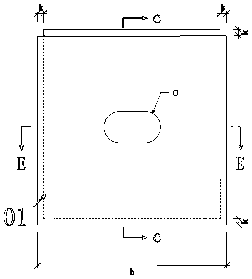
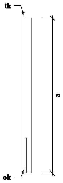
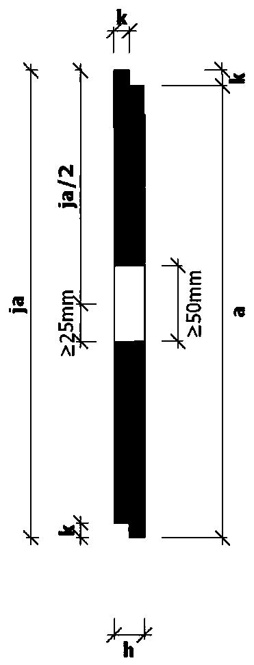
[0174] Embodiment 1. The modular yin and yang formwork system with square sill edge, as shown in Figure 1-15, consists of the following parts:

[0175] 1. The main part of the system: "Square sill-shaped edge modular yin-yang formwork" (abbreviation: "Shan-style formwork");

[0176] 2. Main accessories of the system: "Synthetic screw 09 with inner threaded sleeve at the top of the arc ring" (abbreviation: "Synthetic screw 09");

[0177] 3. Common accessories: "Eccentric selection threaded hole formwork cover" (abbreviation: "formwork cover");

[0178] 4. Other components: The steel pipes, fasteners, square bars, umbrella cards and other components in the original system are inherited and retained.

[0179] Note: The common accessories are the common accessories of the main parts of the system and the main parts of the system

[0180] System master

[0181] The main part of the system: the basic features of the "Canyon formwork" include:

[0182] 1. "Square sill edge" is a fo...


PUM


Abstract

The invention discloses a square ridge type edge modular female and male formwork system, and belongs to building formworks. On the basis of currently widely adopted planar and straight side-edge mechanism wood clamping plates and bamboo glue plate formworks, the edge structure of the formworks and the positions and structures of threaded rod holes are formed; a series of main components, main accessories and accessories of the system such as functions and structures of screw rods are subjected to system modification; and the modified formworks are changed into difficult-to-corrode and undamaged turnover materials from the current situation of being prone to corrosion, disassemble and damage. Therefore, the whole life cycle of the formwork is greatly prolonged. All the advantages of the original system are basically continued through the modified system, and the economical efficiency is greatly improved in a geometrical progression proportional expression manner. Meanwhile, the defectsof low section control precision, easy slag inclusion of joint seams, necking, slurry leakage and the like are overcome, the technical content of construction of the building formwork is greatly improved, and the erection development of the green and environment-friendly business is promoted.

Description

technical field [0001] The invention belongs to building formwork, specifically: a square sill-shaped edge modularized yin-yang formwork system (abbreviation: "sill-form formwork" system). Background technique [0002] The templates widely used in the formwork system of cast-in-place concrete structures in construction projects are basically "machine-made boards" with a thickness of 14-20 mm and flat edges (collectively referred to as machine-made wood plywood and bamboo plywood). , due to the limitations of the raw materials (strength, toughness and surface corrosion resistance), especially the severe decline in the corrosion resistance of the "cut surface" of the formwork, and the backward technical means when removing the formwork, it is very easy to corrode Such templates result in low reuse rates. In the case that the means of “cutting” and demolition are still lagging behind, and these two states have not been managed for a while, even if it is possible to consider im...

Claims


Application Information

Patent Timeline
IPC IPC(8): E04G9/04E04G9/10E04G17/00E04G17/065
CPCE04G9/04E04G9/10E04G17/001E04G17/0655
Inventor 赵克勤
Owner 赵克勤
Learn More