
Shock absorber and elastic vibration damping device

A vibration damping device and technology of shock absorbers, which are applied to shock absorbers, shock absorbers, springs/shock absorbers, etc., can solve the problems of insufficient stiffness, large space occupied by shock absorbers, and no vibration reduction effect, etc. The effect of improving bearing capacity and fatigue resistance, simple and beautiful appearance, and enhancing practicability

Inactive Publication Date: 2020-02-28
SOLEE WUHAN SCI & TECH
View PDF7 Cites 2 Cited by
  • Summary
  • Abstract
  • Description
  • Claims
  • Application Information

AI Technical Summary

Problems solved by technology

[0002] At present, the shock absorbers used in products mostly adopt the form of specific damping combinations such as electric, magnetic, hydraulic, piston rod, valve body and spring. These forms require auxiliary equipment to play a role, and are mostly used in large power equipment or precision instruments. Although these shock absorbers have good vibration damping effect in some specific directions, they have almost no vibration damping effect in other directions than the specific direction, and this type of shock absorber takes up a lot of space, has a complicated structure, and has low manufacturing and maintenance costs. It is relatively high and requires specialized equipment personnel to install it. At the same time, due to the limited scope of application, the replacement of different shock absorbers is not strong, and it is difficult to be widely used.
[0003] The patent application documents of publication numbers CN207893032U and CN105156537A all disclose a metal spherical shock absorber, but the above-mentioned shock absorber has a poor damping effect in the torsional direction. Secondly, in order to ensure the damping effect, the material used for the shock absorber under this design The elastic modulus will be small, which will lead to insufficient rigidity, and it is easy to produce plastic deformation due to long-term compression and stretching during use, which will further lead to a decrease in the fatigue resistance of the material and a rapid decline in the longitudinal vibration damping effect, which will eventually lead to the reduction of vibration. Vibrating ball loses vibration damping effect

Method used


Image

  • Shock absorber and elastic vibration damping device
  • Shock absorber and elastic vibration damping device
  • Shock absorber and elastic vibration damping device

Examples


Embodiment 1

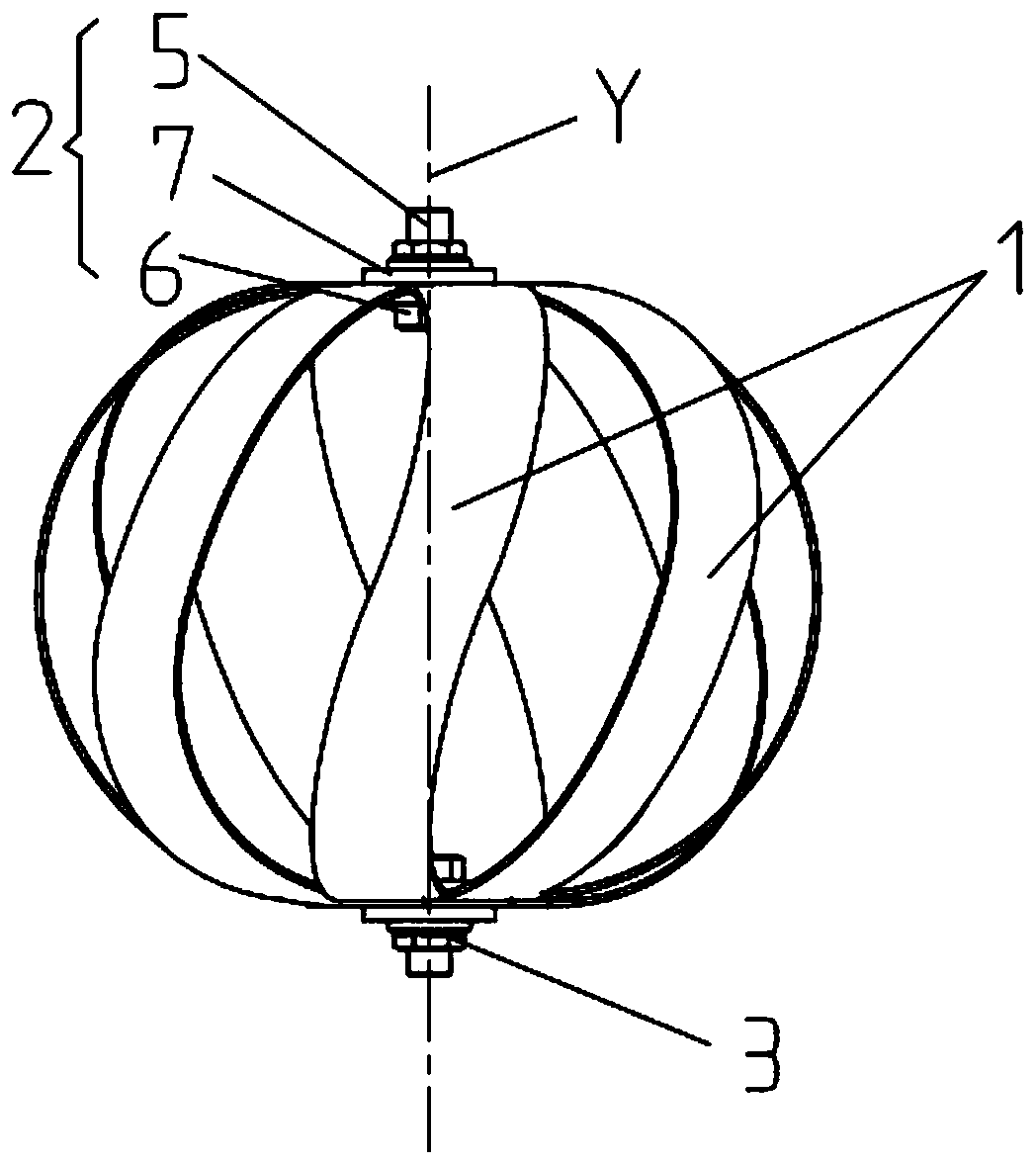
[0038] Such as Figure 1a-1b As shown, the shock absorber in this embodiment includes: several elastic elements 1, upper fasteners 2 and lower fasteners 3, and the upper fasteners 2 and lower fasteners 3 are arranged coaxially, In this embodiment, the upper fastener 2 and the lower fastener 3 both include: bolts 5, nuts 6 and washers 7; the first connection position of each elastic element 1 is connected to the upper fastener 2. The second connection position of each annular elastic element 1 is connected to the lower fastener 3, so that several elastic elements 1 are centered on the common axis Y of the upper fastener 2 and the lower fastener 3, The circumferential direction is arranged as a sphere or an ellipsoid;

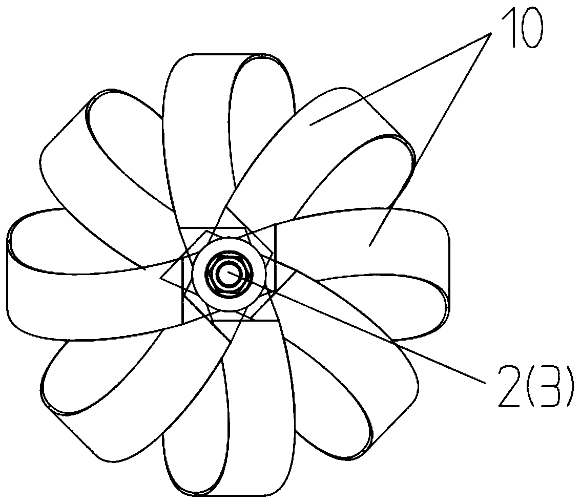
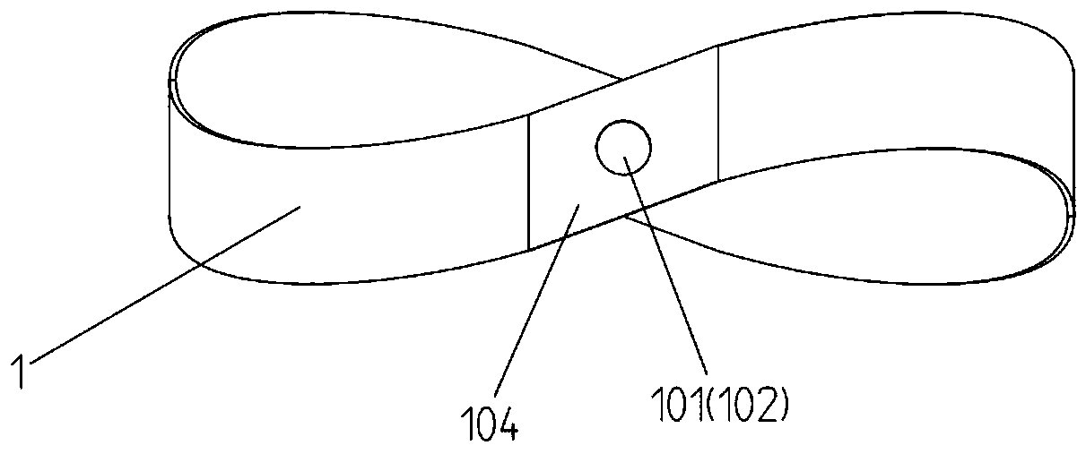
[0039] In this example, if Figure 2a-2b As shown, at least one of the elastic elements 1 is a "∞"-shaped Mobius ring structure, which is connected to the other end after twisting one end of the strip-shaped shrapnel unit 10 by 180° (such as butt joint or lap j...

Embodiment 2

[0044] This embodiment provides an elastic damping assembly, such as Figure 4 As shown, it includes: a vibration damping assembly; a first connecting plate 100 connected to one end of the vibration damping assembly; and / or a second connecting plate 200 connected to one end of the vibration damping assembly.

[0045] Specifically, the damping assembly includes a first damping unit 300 and / or a second damping unit 300', wherein the first damping unit is the damper described in Embodiment 1, and the The first connecting plate 100 is connected to the upper fastener 2 , and / or the second connecting plate 200 is connected to the lower fastener 3 .

[0046] The second damping unit 300' is similar in structure to the first damping unit 300, as Figures 5a-5b As shown, the second damping unit 300' includes: several damping pieces 1', first fasteners 2' and second fasteners 3', and the first fasteners 2' and the second fasteners The two fasteners 3' are coaxially arranged; the first ...

Embodiment 3

[0050] The only difference between this embodiment and Embodiments 1 and 2 is that Figure 10-11 As shown, the strip-shaped elastic piece unit 10 / vibration damping sheet 1' includes: a first elastic piece unit 401 and / or a second elastic piece unit 402, preferably, the first elastic piece unit 401 and the second elastic piece unit 402 are arranged at intervals , to form a sandwich structure, and the first elastic piece 401 and the second elastic piece 402 are correspondingly provided with pin holes 403, and connecting parts such as pins pass through the pin holes 403 on the first elastic piece 401 and the second elastic piece 402 in order to connect all The first elastic piece 401 and the second elastic piece 402; at the same time, one or both of the first elastic piece 401 and the second elastic piece 402 are made of metal or rubber or a combination of metal and rubber , such as by covering the surface of the metal with a rubber layer or made of other elastic-plastic material...


PUM


Abstract

The invention discloses a shock absorber and an elastic vibration damping device. The shock absorber comprises a plurality of elastic elements, an upper fastener and a lower fastener. The upper fastener and the lower fastener are coaxially arranged. The first connecting position of each elastic element is connected with the upper fastener, and the second connecting position of each annular elasticelement is connected with the lower fastener, so that the elastic elements are arranged with the common axis of the upper fastener and the lower fastener as the center and are arranged in a sphere oran ellipsoidal body in the circumferential direction. The at least one elastic element is formed by connecting the end, twisted by 180 degrees, of a strip-shaped elastic piece unit with the other endof the strip-shaped elastic piece. The shock absorber and the elastic vibration damping device have extremely high vibration damping efficiency and have good vibration damping effect in directions such as transverse, longitudinal and torsional shearing in the space, and meanwhile, the bearing capacity and the fatigue resistance are high.

Description

technical field [0001] The invention relates to the field of vibration damping engineering, in particular to a vibration damper and an elastic vibration damping device. Background technique [0002] At present, the shock absorbers used in products mostly adopt the form of specific damping combinations such as electric, magnetic, hydraulic, piston rod, valve body and spring. These forms require auxiliary equipment to play a role, and are mostly used in large power equipment or precision instruments. Although these shock absorbers have good vibration damping effect in some specific directions, they have almost no vibration damping effect in other directions than the specific direction, and this type of shock absorber takes up a lot of space, has a complicated structure, and has low manufacturing and maintenance costs. It is relatively high and requires specialized equipment personnel to install. At the same time, because of the limited scope of application, the replacement bet...

Claims


Application Information

Patent Timeline
Patent Type & Authority Applications(China)
IPC IPC(8): F16F7/00
CPCF16F7/00F16F2224/025F16F2234/08
Inventor 杨芬韩春晖
Owner SOLEE WUHAN SCI & TECH
Learn More