Dynamic strain calibration method with continuously adjustable frequency
A technology of dynamic strain and calibration method, which is applied in the direction of measuring devices and instruments, can solve the problems of principle error, inability to meet structural dynamic strain measurement, lack of calibration method and device for dynamic characteristics of strain gauge, etc., and achieve continuous calibration frequency and amplitude adjustable effect
- Summary
- Abstract
- Description
- Claims
- Application Information
AI Technical Summary
Problems solved by technology
Method used
Image
Examples
Embodiment 1
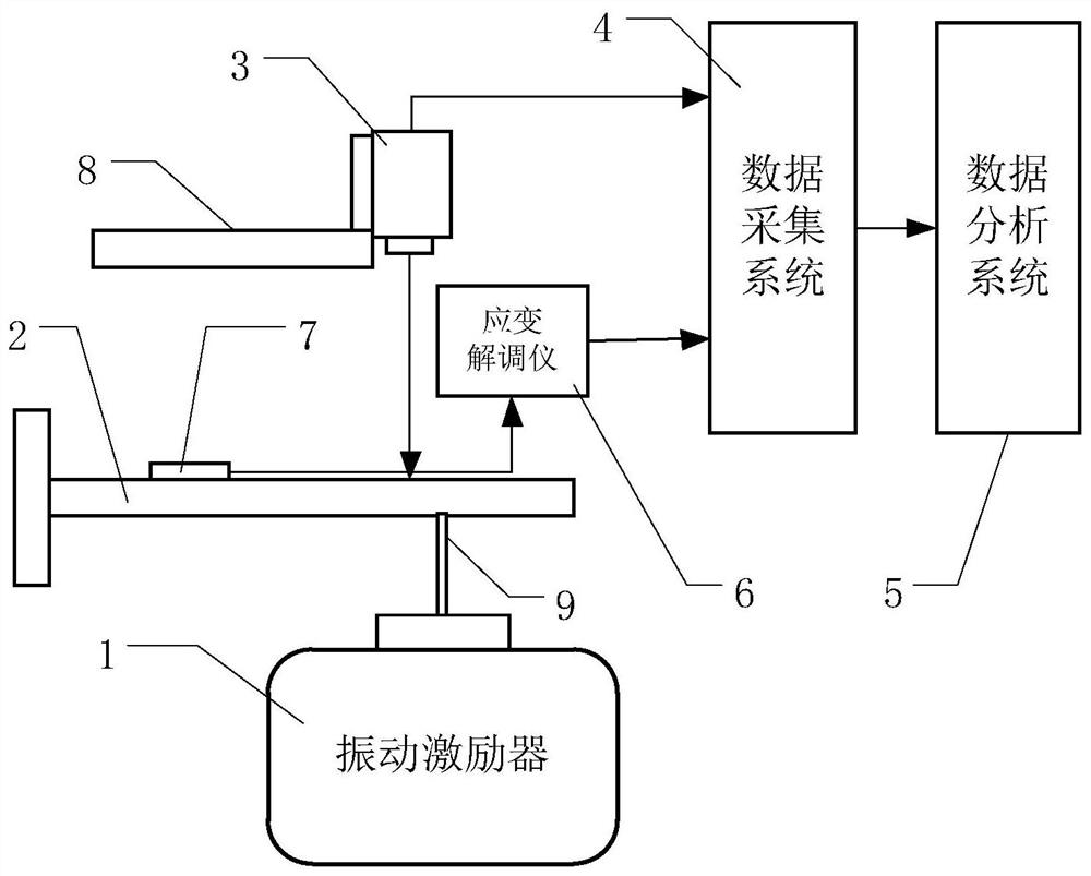
[0032] Such as figure 1 As shown, the frequency continuously adjustable dynamic strain calibration method disclosed in this embodiment is based on the frequency continuously adjustable dynamic strain calibration device disclosed in this embodiment. The dynamic strain calibration device includes a vibration exciter 1, a cantilever beam 2, Laser interferometer 3, data acquisition system 4, data analysis system 5, strain demodulator 6, calibrated strain gauge 7, micro-displacement mechanism 8, flexible rod 9.
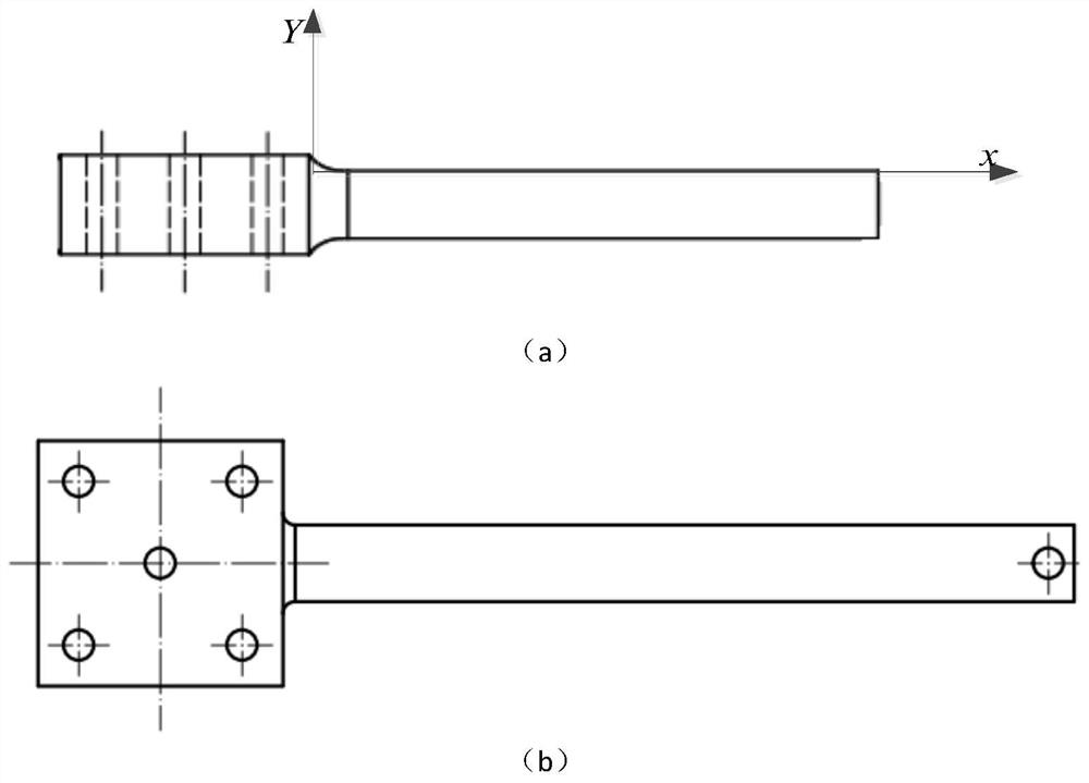
[0033] Such as figure 2 As shown, first select a cantilever beam 2 with a constant section with a length of 200 mm, a thickness of 10 mm, and a first-order natural frequency of about 1 kHz. A rectangular cantilever beam with a constant cross section is used. First, one end of the cantilever beam 2 is fixed, and the abscissa of the fixed end is 0. One end is installed on the vibration exciter 1 through a flexible rod 9, which requires the flexible rod to have a higher fir...
Embodiment 2
[0045] The present invention will be further described below in conjunction with the accompanying drawings and the embodiment based on the second method.
[0046] Such as figure 2As shown, first select a cantilever beam 2 with a constant cross-section whose length is 200 mm, thickness is 10 mm, and the first-order natural frequency is about 1 kHz. One end of the cantilever beam 2 is fixed, and the other end is installed on the modal exciter 1 through a flexible rod 9. It is required that the flexible rod has a higher first-order resonance frequency and can have a certain lateral displacement under the action of lateral force. The strain gauge 7 to be calibrated is installed on the upper surface of the cantilever beam 2 and connected with the strain interrogator 6 . The laser interferometer 3 is installed on the micro-displacement mechanism 8 . The laser beam of the laser interferometer 3 is adjusted so that it can measure the displacement of the upper surface of the cantile...
PUM
 Abstract
Description
Claims
Application Information
 - R&D
- Intellectual Property
- Life Sciences
- Materials
- Tech Scout
- Unparalleled Data Quality
- Higher Quality Content
- 60% Fewer Hallucinations
Browse by: Latest US Patents, China's latest patents, Technical Efficacy Thesaurus, Application Domain, Technology Topic, Popular Technical Reports.
© 2025 PatSnap. All rights reserved.Legal|Privacy policy|Modern Slavery Act Transparency Statement|Sitemap|About US| Contact US: help@patsnap.com


