Power control circuit

A power control circuit and circuit technology, applied in the electronic field, can solve the problems of no self-recovery and low safety, and achieve the effect of improving safety and reliability

Inactive Publication Date: 2020-02-28
SUZHOU LANGCHAO INTELLIGENT TECH CO LTD
View PDF11 Cites 1 Cited by
  • Summary
  • Abstract
  • Description
  • Claims
  • Application Information

AI Technical Summary

Problems solved by technology

[0003] However, the existing backup power system usually only uses fuses as a protection scheme for the entire backup power system, which is less safe, and the existing backup power system does not have the function of self-recovery after the fault is eliminated

Method used


Image

  • Power control circuit
  • Power control circuit
  • Power control circuit

Examples


no. 1 example

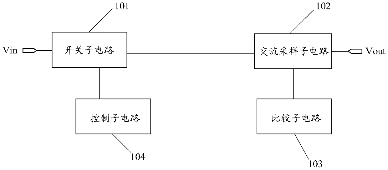
[0027] figure 1 It is a schematic structural diagram of the first embodiment of the power supply control circuit of the present application, such as figure 1 As shown, the power control circuit provided by this embodiment includes: a power input terminal Vin, a load output terminal Vout, a switch subcircuit 101 , an AC sampling subcircuit 102 , a comparison subcircuit 103 and a control subcircuit 104 .

[0028] The switch sub-circuit 101 is respectively connected with the power input terminal Vin, the AC sampling sub-circuit 102 and the control sub-circuit 104, and is used to receive the control signal of the control sub-circuit 104, and control its own on-off state according to the control signal; the AC sampling sub-circuit 102 is respectively It is connected with the switch subcircuit 101, the comparison subcircuit 103 and the load output terminal Vout for collecting analog current signals or analog voltage signals, and outputting to the comparison subcircuit 103; the compa...

no. 2 example

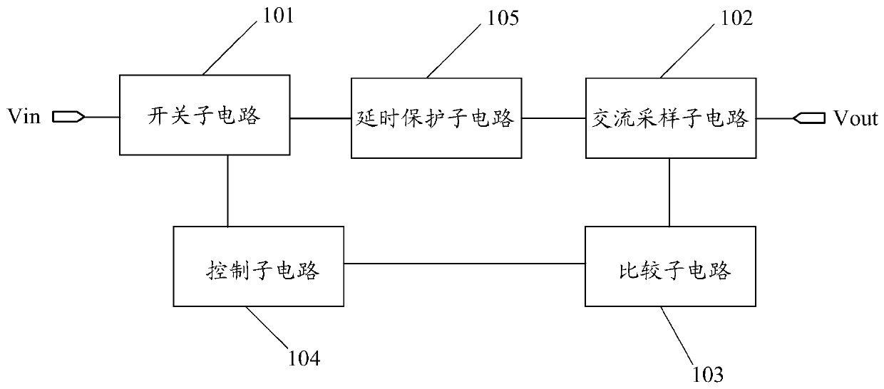
[0042] figure 2 It is a schematic structural diagram of the second embodiment of the power control circuit of the present application. This embodiment is an extension of the foregoing first embodiment, and its main structure is basically the same as that of the foregoing first embodiment, except that the power supply control circuit of this embodiment includes a delay protection sub-circuit. Such as figure 2 As shown, the power supply control circuit provided in this embodiment includes: power supply input terminal Vin, load output terminal Vout, switch subcircuit 101, delay protection subcircuit 105, AC sampling subcircuit 102, comparison subcircuit 103 and control subcircuit 104 .

[0043] Wherein, the switch sub-circuit 101 is respectively connected with the power supply input terminal Vin, the delay protection sub-circuit 105 and the control sub-circuit 104, and is used to receive the control signal of the control sub-circuit 104, and control the on-off state of itself...

no. 3 example

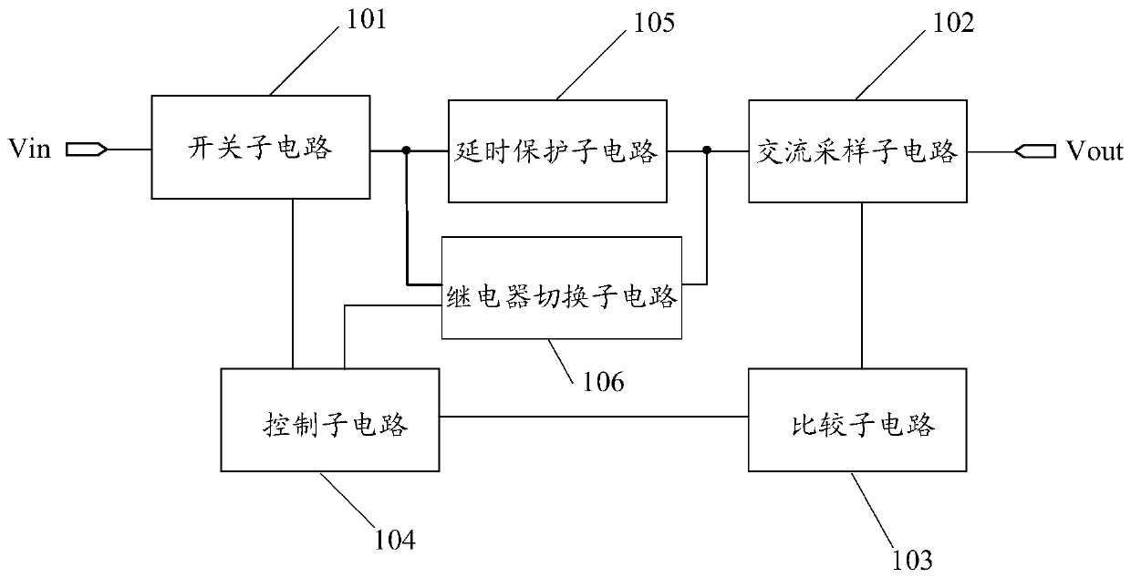
[0048] image 3 It is a schematic structural diagram of the third embodiment of the power control circuit of the present application. This embodiment is an extension of the foregoing second embodiment, and its main structure is basically the same as that of the foregoing second embodiment, except that the power control circuit of this embodiment includes a relay switching sub-circuit. Such as image 3 As shown, the power supply control circuit provided by this embodiment includes: power supply input terminal Vin, load output terminal Vout, switch subcircuit 101, delay protection subcircuit 105, relay switching subcircuit 106, AC sampling subcircuit 102, comparison subcircuit 103 and control sub-circuit 104.

[0049] Wherein, the switch sub-circuit 101 is respectively connected with the power input terminal Vin, the delay protection sub-circuit 105, the relay switching sub-circuit 106 and the control sub-circuit 104, and is used to receive the control signal of the control su...


PUM


Abstract

The embodiment of the invention discloses a power control circuit, which comprises a power input end, a load output end, a switch sub-circuit, an alternating-current sampling sub-circuit, a comparisonsub-circuit and a control sub-circuit. The switch sub-circuit is used for receiving a control signal of the control sub-circuit and controlling the on-off state of the switch sub-circuit according tothe control signal. The alternating-current sampling sub-circuit is used for collecting an analog current signal or an analog voltage signal and outputting the analog current signal or the analog voltage signal to the comparison sub-circuit. The comparison sub-circuit is used for converting the analog current signal or the analog voltage signal into a digital voltage signal, comparing the digitalvoltage signal with a preset voltage threshold to obtain a first comparison result and outputting the first comparison result to the control sub-circuit. The control sub-circuit is used for outputting a first control signal to the switch sub-circuit according to the first comparison result. According to the embodiment of the invention, the current and voltage abnormality condition of a standby power system is detected, the standby power system has a self-recovery function after a fault is removed, and the safety and reliability of the standby power system are improved.

Description

technical field [0001] Embodiments of the present invention relate to but are not limited to the field of electronic technology, and in particular, relate to a power supply control circuit. Background technique [0002] In order to ensure the reliability of power supply, the backup power system has gradually become an indispensable part of some important power supply systems. When the main power supply fails due to the interruption of the mains power supply, the system will automatically switch to the backup power system. Thereby ensuring that the equipment can work reliably. [0003] However, the existing backup power system usually only uses fuses as a protection scheme for the entire backup power system, which has low safety, and the existing backup power system does not have the function of self-recovery after the fault is eliminated. Contents of the invention [0004] The embodiment of the present invention provides a power supply control circuit, which can improve t...

Claims


Application Information

Patent Timeline
Patent Type & Authority Applications(China)
IPC IPC(8): H02J9/06G01R19/165H02H3/06
CPCG01R19/16547H02H3/066H02J9/06Y02B70/30Y04S20/20
Inventor 李星辰
Owner SUZHOU LANGCHAO INTELLIGENT TECH CO LTD
Why Eureka
Try Eureka