An Mbus interface control circuit

A technology of interface control and circuit, applied in the direction of electrical digital data processing, instruments, etc., can solve the problems of sampling data confusion, low reliability, bulky volume, etc., to achieve improved stability and reliability, fast response speed, and high integration Effect

Pending Publication Date: 2019-03-15
COMBA TELECOM SYST CHINA LTD
View PDF0 Cites 0 Cited by
  • Summary
  • Abstract
  • Description
  • Claims
  • Application Information

AI Technical Summary

Problems solved by technology

[0004] 1) The strength of the received signal and the stability of the signal output are improved through the logical combination of the pre-filter differential amplifier circuit and the signal output circuit, thereby increasing the number of nodes loaded, improving the load capacity of the circuit and the anti-interference ability of the circuit signal , this scheme does not have the function of abnormal current detection. Once the overcurrent problem such as short circuit occurs in the rear pole, it is easy to cause the circuit of the previous stage to burn out and cannot be recovered; in addition, because the scheme uses multi-stage amplifier circuits and filter circuits, making Only the MBUS receiving circuit is very complicated. If additional sending related circuits are added, the entire MBUS interface will be more complicated, bulkier and more costly.
[0005] 2) The circuit is built with discrete components, and it must cooperate with controllers such as microcontrollers to realize complete overload protection, signal

Method used


Image

  • An Mbus interface control circuit
  • An Mbus interface control circuit
  • An Mbus interface control circuit

Examples


Embodiment Construction

[0032] Exemplary embodiments of the present disclosure will be described in more detail below with reference to the accompanying drawings. Although exemplary embodiments of the present disclosure are shown in the drawings, it should be understood that the present disclosure may be embodied in various forms and should not be limited by the embodiments set forth herein. Rather, these embodiments are provided for more thorough understanding of the present disclosure and to fully convey the scope of the present disclosure to those skilled in the art.

[0033]Those skilled in the art can understand that, unless otherwise defined, all terms (including technical terms and scientific terms) used herein have the same meaning as commonly understood by those of ordinary skill in the art to which this invention belongs. It should also be understood that terms, such as those defined in commonly used dictionaries, should be understood to have meanings consistent with the meanings in the con...


PUM


Abstract

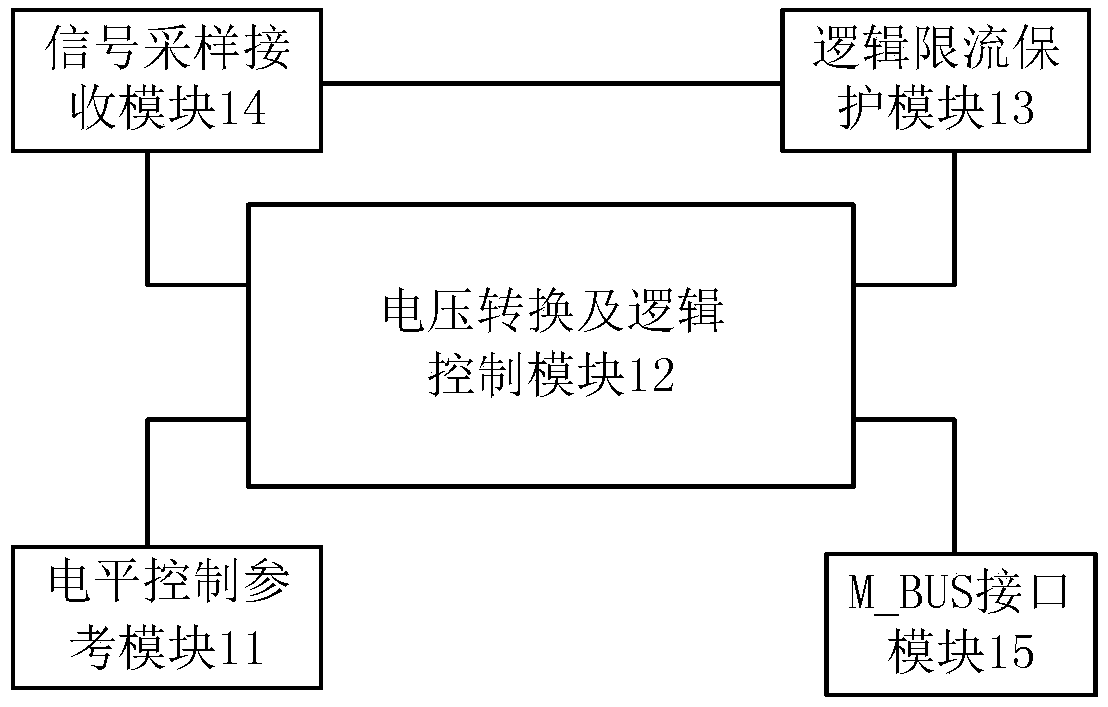
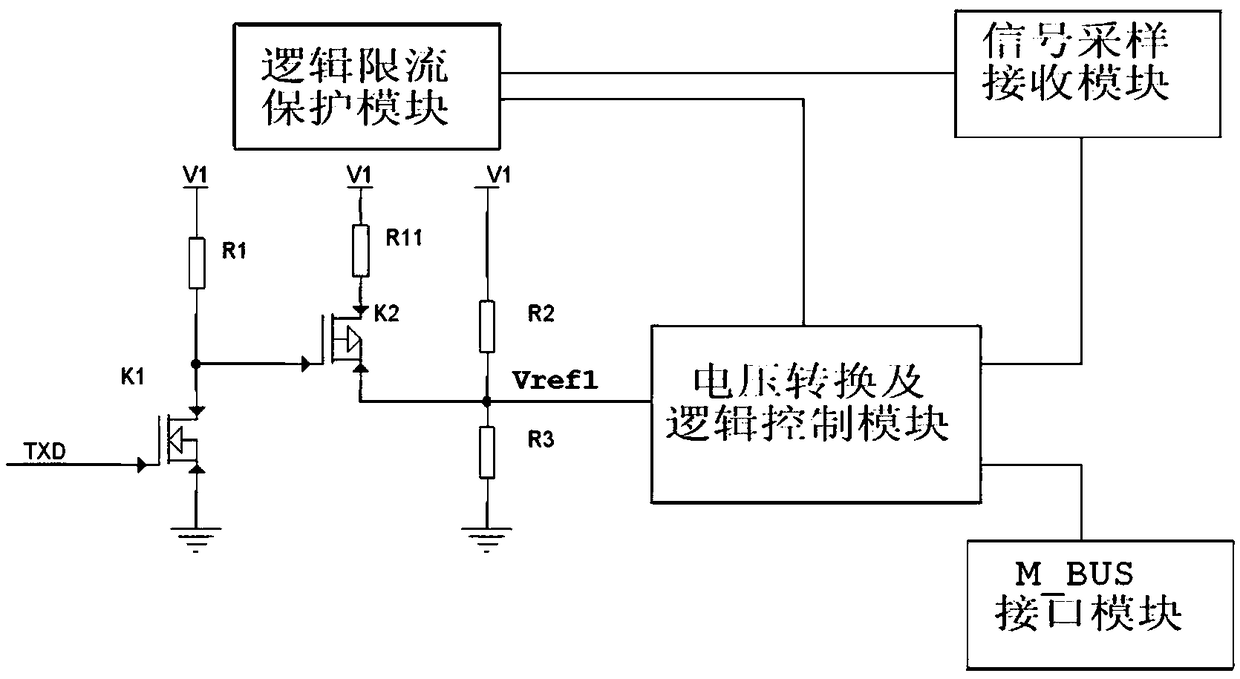
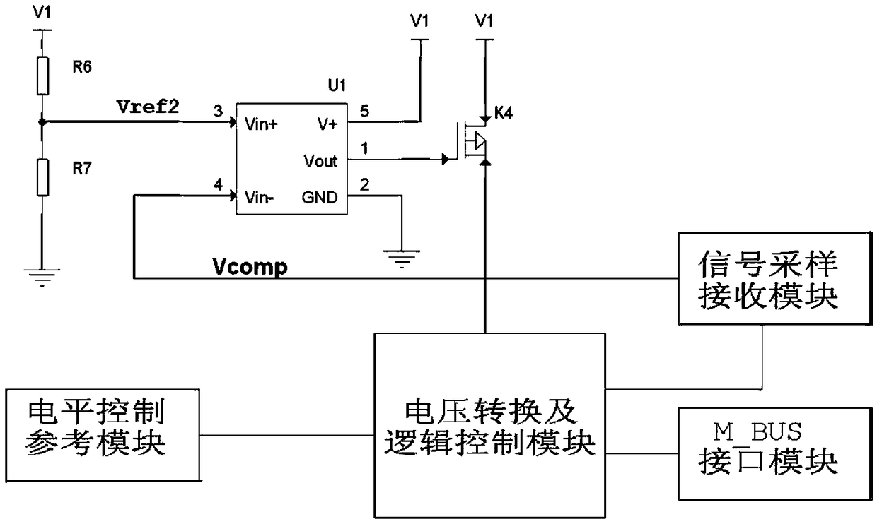
The invention provides an Mbus interface control circuit, comprising a level control reference module which generates a reference voltage according to a control signal sent by a host computer, and sends the reference voltage to a voltage conversion and logic control module. The signal sampling receiving module performs current signal sampling on the voltage conversion and logic control module, andgenerates a data signal transmitted to the host computer according to the sampled signal. A logic current limit protection module generates a control voltage accord to a sampling signal and sends that control voltage to a voltage conversion and logic control module. The voltage conversion and logic control module controls the current signal of the M_BUS interface module to be turned on or off according to the reference voltage and the control voltage, and transmits the current signal to the signal sampling and receiving module. An M_BUS interface module for connecting subsequent MBUS slave circuits. The invention realizes overcurrent protection, power-off and signal transmission control of the MBUS circuit through logic control between hardware circuits, reduces loss to a maximum extent,and greatly improves stability and reliability of the MBUS circuit.

Description

technical field [0001] The invention relates to the technical fields of communication and the Internet of Things, in particular to an Mbus interface control circuit. Background technique [0002] The meter bus (M-Bus) is a new type of bus structure. The main feature of M-Bus is to supply power and transmit serial data at the same time through two non-polar transmission lines, and each substation (confirmed by different ID) is connected in parallel On the M-Bus bus. When M-Bus is used in the energy consumption intelligent management system of various instruments or related devices, relevant data or signals can be collected and transmitted to the concentrator, and then transmitted to the master station through the corresponding interface. The use of M-Bus can greatly simplify the wiring and connection of energy consumption intelligent management systems such as residential quarters and office places, and has the characteristics of simple structure, low cost and high reliabili...

Claims


Application Information

Patent Timeline
IPC IPC(8): G06F13/38
CPCG06F13/382
Inventor 张东闯郭聪聪洗启源
Owner COMBA TELECOM SYST CHINA LTD
Why Eureka
Try Eureka