Permanent magnet synchronous motor rotor of mixed magnetic steel

A technology of permanent magnet synchronous motors and magnets, which is applied in the direction of magnetic circuit rotating parts, magnetic circuits, electrical components, etc., and can solve the problem of small proportion of motor reluctance torque, easy demagnetization, large consumption of motor magnets, etc. question

Pending Publication Date: 2020-02-28
ZHEJIANG LOONGSON ELECTRIC DRIVE TECH CO LTD
View PDF0 Cites 0 Cited by
  • Summary
  • Abstract
  • Description
  • Claims
  • Application Information

AI Technical Summary

Problems solved by technology

[0003] The traditional arrangement of rotor magnets includes "one" shape, "V" shape and "V"+"one" shape, but the motor reluctance torque of the above magnetic circuit structures is not large, relatively large consumption
In order to increase the proportion of the reluctance torque of the motor and improve the magnetic field weakening capability of the motor, double "V" and multi-"V" magnet topologies have also begun to appear in recent years. With the increase in the number of layers, the moto

Method used


Image

  • Permanent magnet synchronous motor rotor of mixed magnetic steel

Examples


Embodiment

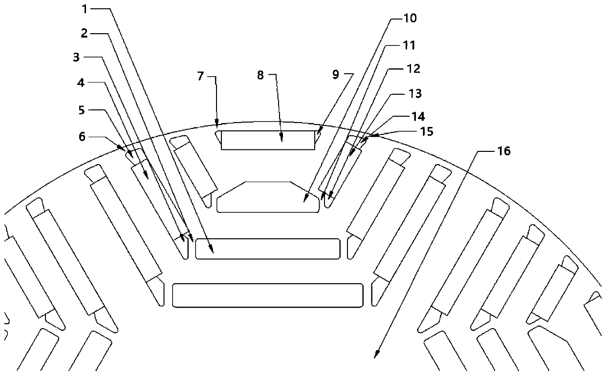
[0022] Such as figure 1 Shown, the permanent magnet synchronous motor rotor of hybrid magnetic steel of the present invention, it is made up of first magnetic steel 8, second magnetic steel 13, the 3rd magnetic steel 4 and rotor iron core 16, the first magnetic steel 8, the second The magnets 13 and the third magnets 4 are alternately distributed and embedded in the rotor core 16, and form several magnetic poles; each pole has N layers of magnets, N is a natural number ≥ 3, the first magnets 8, the second The second magnetic steel 13 and the third magnetic steel 4 are alternately distributed on the magnetic poles in sequence.

[0023] For example, each magnetic pole of the rotor core 16 has N (N is a natural number greater than or equal to 3) layers of magnetic steel, the first layer is 1 piece of first magnetic steel 8, the second layer is 2 pieces of second magnetic steel 13, and the second layer is 2 pieces of second magnetic steel 13. The third layer is composed of two th...


PUM


Abstract

The object of the present invention is to disclose a permanent magnet synchronous motor rotor of mixed magnetic steel, which is composed of first magnetic steel, second magnetic steel, third magneticsteel, and a rotor core. The first, second and third magnetic steel are alternately distributed and embedded in the rotor core to form a plurality of magnetic poles. Each magnetic pole has N layers ofmagnetic steel, wherein N is a natural number greater than or equal to 3. The first, second and third magnetic steel are alternately distributed on the magnetic poles in sequence. Compared with the prior art, the multilayer magnetic steel arrangement can easily obtain a good magnetic flux concentration effect and pole arc coefficient control, solves the contradiction between the structural strength and the magnetic isolation effect of the tangential magnetic steel arrangement, and effectively reduces the performance degradation caused by the pole leakage reactance of the motor. A layer of themultilayer magnetic steel close to the outer circle of the rotor core is the radial magnetic steel to further enhance the magnetic flux concentration effect to achieve the object of the present invention.

Description

technical field [0001] The invention relates to a motor rotor, in particular to a permanent magnet synchronous motor rotor with mixed magnetic steel. Background technique [0002] In the prior art, the reluctance torque generated by the asymmetry of the rotor magnetic circuit of the built-in permanent magnet synchronous motor is beneficial to improve the overload capacity and power density of the motor, and has been applied more and more. [0003] The traditional arrangement of rotor magnets includes "one" shape, "V" shape and "V"+"one" shape, but the motor reluctance torque of the above magnetic circuit structures is not large, The consumption is relatively large. In order to increase the proportion of the reluctance torque of the motor and improve the magnetic field weakening capability of the motor, double "V" and multi-"V" magnet topologies have also begun to appear in recent years. With the increase in the number of layers, the motor's The structural strength will det...

Claims


Application Information

Patent Timeline
IPC IPC(8): H02K1/27
CPCH02K1/2773H02K2213/03
Inventor 王丽
Owner ZHEJIANG LOONGSON ELECTRIC DRIVE TECH CO LTD
Why Eureka
Try Eureka