Structure-reinforced photovoltaic panel fixing frame and mounting method

A photovoltaic panel and reinforced technology, applied in the field of power equipment, can solve the problems of reduced power generation efficiency, prone to breakage, photovoltaic panels can not reach the optimal sunlight angle, etc., and achieves easy angle adjustment, small amount of engineering, and power generation efficiency. high effect

Pending Publication Date: 2020-02-28
GUIZHOU ELECTRIC POWER DESIGN INST
View PDF0 Cites 3 Cited by
  • Summary
  • Abstract
  • Description
  • Claims
  • Application Information

AI Technical Summary

Problems solved by technology

[0002] In order to make full use of land resources, some photovoltaic power stations will choose to build in rocky desertification mountainous areas that cannot be cultivated. The problem encountered in building photovoltaic power stations in rocky desertification mountainous areas is that the angle of the traditional photovoltaic panel fixing frame used in mountainous areas is fixed. Only rely on the main support rod and the pull rope around the installation frame. During installation, adjust the length of the pull rope around the installation frame. Since the main support rod and the installation frame are connected by universal joints, the angle of the installation frame will change with the length of the pull rope. changes, but the problem with this support frame is that,
[0003] 1) After a long period of natural weathering or heat expansion and contraction, the pull rope is prone to breakage, which makes the angle of the photovoltaic panel change and cannot reach the best sunlight angle, reducing power generation efficiency;

Method used


Image

  • Structure-reinforced photovoltaic panel fixing frame and mounting method
  • Structure-reinforced photovoltaic panel fixing frame and mounting method
  • Structure-reinforced photovoltaic panel fixing frame and mounting method

Examples


Embodiment 1

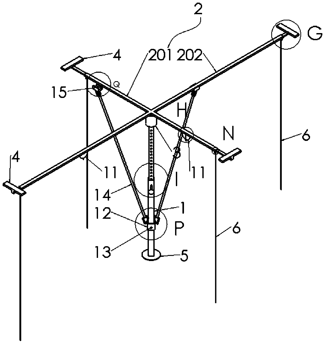
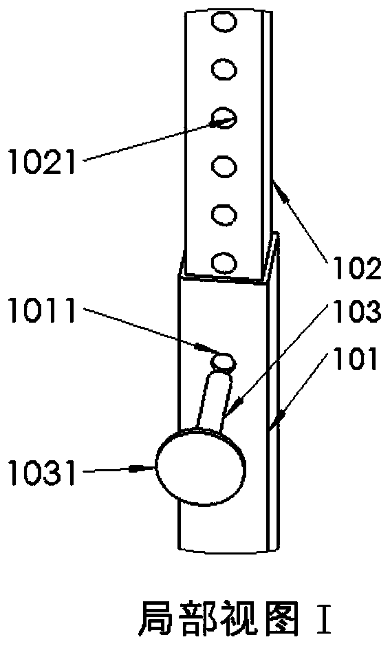
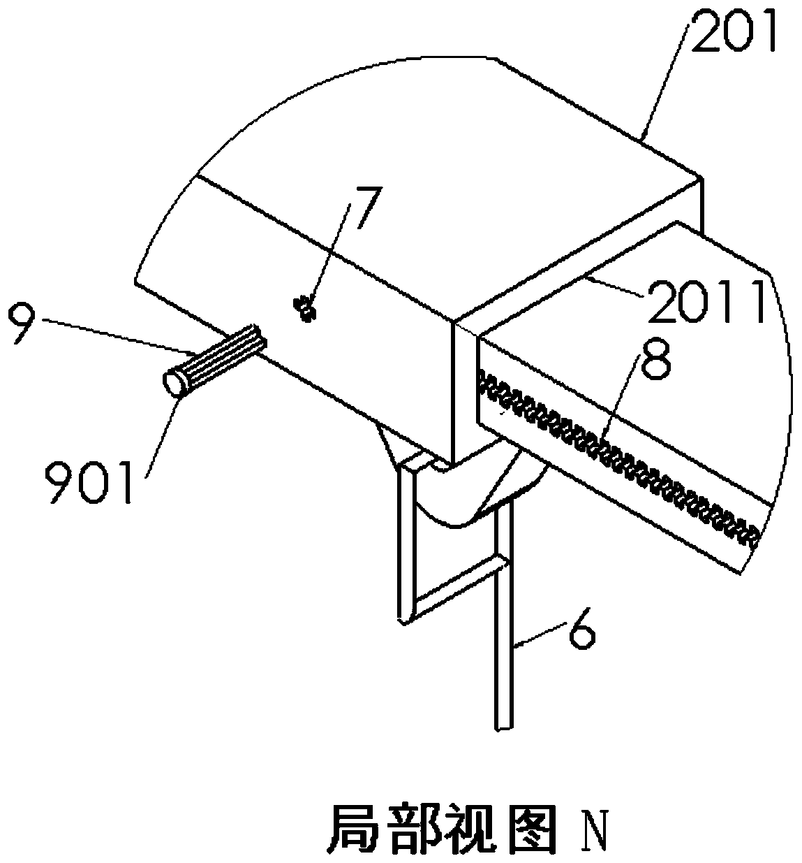
[0055] Implementation Example 1: Reference Figure 1 to Figure 13, a structurally reinforced photovoltaic panel fixing frame, comprising: a main support rod 1, the lower end of the main support rod 1 is fixedly connected to a flange 5; a mounting frame 2, and the middle part of the lower surface of the mounting frame 2 is fixedly connected to a universal joint 3 , the mounting frame 2 is connected to the upper end of the main support rod 1 through the universal joint 3, and a stay rope 6 is connected to each mounting frame 2 located at four directions of the universal joint 3, front, rear, left, and right, and the mounting frame 2 is ferromagnetic. Material: sliding sleeve 12, the sliding sleeve 12 is slidably connected on the main support rod 1, the side wall of the sliding sleeve 12 is provided with a screw hole passing through the inner and outer walls, and the screw hole is threadedly connected with a bolt 13 matching the screw hole, The sliding sleeve 12 fixes the positio...


PUM


Abstract

The invention discloses a structure-reinforced photovoltaic panel fixing frame, which comprises a main supporting rod, a mounting frame, a sliding sleeve and more than two reinforcing rods. The lowerend of the main supporting rod is fixedly connected with a flange. The middle of the lower surface of the mounting frame is fixedly connected with a universal joint, and the mounting frame is connected with the upper end of the main supporting rod through the universal joint. The mounting frame is connected with a pull rope in each of the front direction, the rear direction, the left direction andthe right direction of the universal joint, and the mounting frame is made of a ferromagnetic material. The sliding sleeve is connected to the main supporting rod in a sliding mode, a screw hole penetrating through the inner wall and the outer wall is formed in the side wall of the sliding sleeve, a bolt matched with the screw hole is connected to the screw hole in a threaded mode, and the position of the sliding sleeve on the main supporting rod is fixed through tightness of the bolt. The lower ends of the reinforcing rods are rotationally connected to the side surface of the sliding sleeve,the upper ends of the reinforcing rods are rotationally connected with suction blocks, and the suction blocks are made of a permanent magnet material. The problem that the angle of a photovoltaic panel is easy to change and the angle of the photovoltaic panel is difficult to fix during installation in the prior art is solved.

Description

technical field [0001] The invention relates to the technical field of electric equipment, in particular to a structurally reinforced photovoltaic panel fixing frame and an installation method. Background technique [0002] In order to make full use of land resources, some photovoltaic power stations will choose to build in rocky desertification mountainous areas that cannot be cultivated. The problem encountered in building photovoltaic power stations in rocky desertification mountainous areas is that the angle of the traditional photovoltaic panel fixing frame used in mountainous areas is fixed. Only rely on the main support rod and the pull rope around the installation frame. During installation, adjust the length of the pull rope around the installation frame. Since the main support rod and the installation frame are connected by universal joints, the angle of the installation frame will change with the length of the pull rope. changes, but the problem with this support ...

Claims


Application Information

Patent Timeline
Patent Type & Authority Applications(China)
IPC IPC(8): H02S20/30H02S20/10F24S30/48F24S30/20
CPCF24S30/20F24S30/48H02S20/10H02S20/30Y02E10/47Y02E10/50
Inventor 唐俊辉韦丹杨洋魏石磊万宇李扬松
Owner GUIZHOU ELECTRIC POWER DESIGN INST
Why Eureka
Try Eureka