
Photographing control method and system based on external flash light source and storage medium

A flash light source and control system technology, which is applied to the parts of TV systems, optics, color TV parts, etc., can solve the problem that the camera function and shooting performance of smart electronic devices cannot be fully utilized, and the work of the flash light source cannot be directly controlled, real-time Difficulty meeting sexual demands

Active Publication Date: 2020-02-28
何建军 +2
View PDF11 Cites 10 Cited by
  • Summary
  • Abstract
  • Description
  • Claims
  • Application Information

AI Technical Summary

Problems solved by technology

The smart electronic device provides a low-power flash light source inside, but the output power of the built-in flash light source is small, and the position is fixed, which cannot meet the requirements of professional photography for ambient light sources
In addition, most of the current smart electronic devices are not specially designed for the use of external flash light sources, so they do not have a dedicated trigger signal output and cannot directly control the work of the flash light source
[0004] Existing technical solutions use Bluetooth, Wi-Fi and other short-distance radio communication methods to trigger an external flash light source, but due to the limitations of the internal operating system and software of smart electronic devices, it is difficult to meet the real-time requirements; the above communication methods need to develop special shooting Software, without the support of the manufacturer, the camera function and shooting performance of the smart electronic device cannot be fully utilized, and high-quality photos with high definition cannot be obtained

Method used


Image

  • Photographing control method and system based on external flash light source and storage medium
  • Photographing control method and system based on external flash light source and storage medium
  • Photographing control method and system based on external flash light source and storage medium

Examples


Embodiment Construction

[0076] In order to more clearly illustrate the embodiments of the present invention or the technical solutions in the prior art, the specific implementation manners of the present invention will be described below with reference to the accompanying drawings. Obviously, the accompanying drawings in the following description are only some embodiments of the present invention, and those skilled in the art can obtain other accompanying drawings based on these drawings and obtain other implementations.

[0077] In order to make the drawing concise, each drawing only schematically shows the parts related to the present invention, and they do not represent the actual structure of the product. In addition, to make the drawings concise and easy to understand, in some drawings, only one of the components having the same structure or function is schematically shown, or only one of them is marked. Herein, "a" not only means "only one", but also means "more than one".

[0078] An embodim...


PUM


Abstract

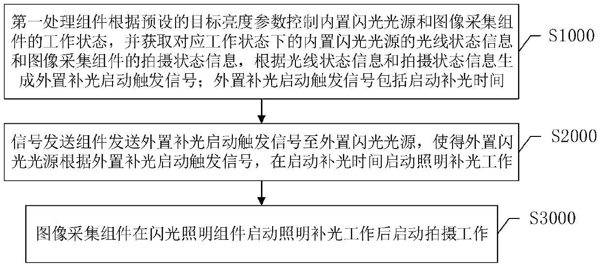
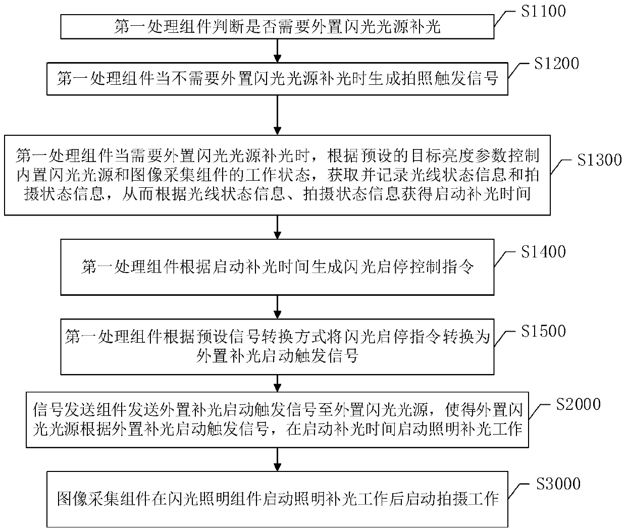
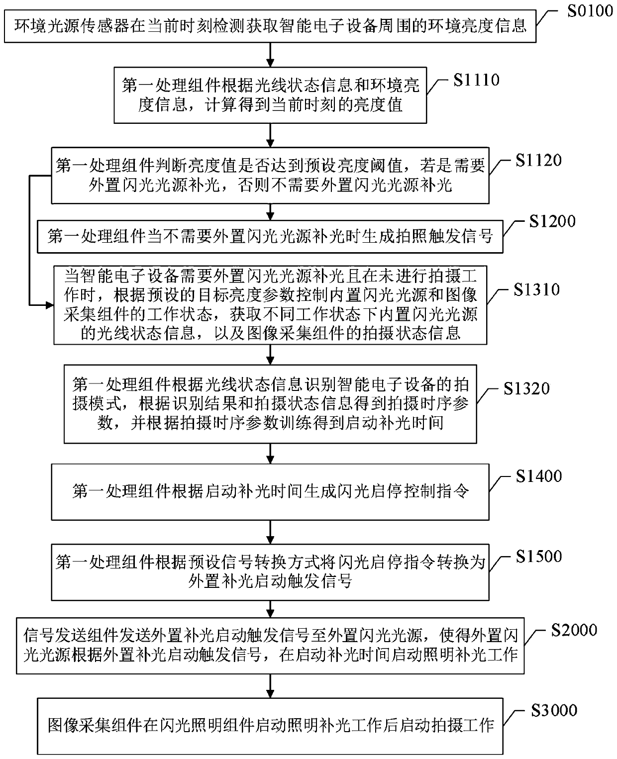
The invention provides a photographing control method and system based on an external flash light source and a storage medium. The method comprises the following steps: 1, preparing a precursor; the first processing assembly controls the working states of the built-in flash light source and the image acquisition assembly according to a preset target brightness parameter; obtaining the light stateinformation of the built-in flash light source and the shooting state information of the image acquisition assembly in the corresponding working state, and generating an external light supplement starting trigger signal according to the light state information and the shooting state information; wherein the external light supplementing starting trigger signal comprises starting light supplementingtime; the signal sending assembly sends an external light supplement starting trigger signal to the external flash light source, so that the external flash light source starts illumination light supplement work at the light supplement starting time according to the external light supplement starting trigger signal; and the image acquisition assembly starts shooting work after the flash illumination assembly starts illumination light supplement work. On the premise that software and hardware of equipment are not changed, the external flash light source is synchronously controlled to perform illumination light supplement during exposure, and the photographing quality is improved.

Description

technical field [0001] The invention relates to the field of portable electronic devices, in particular to a camera control method, system and storage medium based on an external flash light source. Background technique [0002] The flash light source for photography is an important lighting device in the field of picture photography. The flash light source outputs light with a relatively high luminous flux in a short period of time to meet the lighting requirements during the photography process. Flash light sources require an external trigger signal to control short-duration light output. The flash light sources for photography currently on the market mainly use external electrical signals to trigger and control the light output, and some use photoelectric sensors to control the light output by detecting changes in the light intensity of the auxiliary trigger light source. [0003] At present, more and more users start to use smart electronic devices with shooting functio...

Claims


Application Information

Patent Timeline
Patent Type & Authority Applications(China)
IPC IPC(8): H04N5/235G03B15/03
CPCG03B15/03H04N23/74
Inventor 何建军傅懿张勇
Owner 何建军
Learn More