Gas box type blowing wind pipe dust removing device

A technology of spraying blowpipes and dust collectors, which is applied to chemical instruments and methods, separation methods, and separation of dispersed particles. It can solve problems such as poor self-cleaning effect, unfavorable maintenance and installation, and complex structure, so as to facilitate maintenance and improve The effect of flow and overall structure is simple

Pending Publication Date: 2020-03-03
苏州科思瑞得环保科技有限公司
View PDF23 Cites 0 Cited by
  • Summary
  • Abstract
  • Description
  • Claims
  • Application Information

AI Technical Summary

Problems solved by technology

[0003] The Chinese invention patent with the authorized announcement number CN204017578U provides a filter cartridge dust collector. The filter cartridge and the pipeline for blowing air are set independently and installed in the box respectively. The pipeline needs to exte

Method used


Image

  • Gas box type blowing wind pipe dust removing device
  • Gas box type blowing wind pipe dust removing device
  • Gas box type blowing wind pipe dust removing device

Examples


Embodiment 1

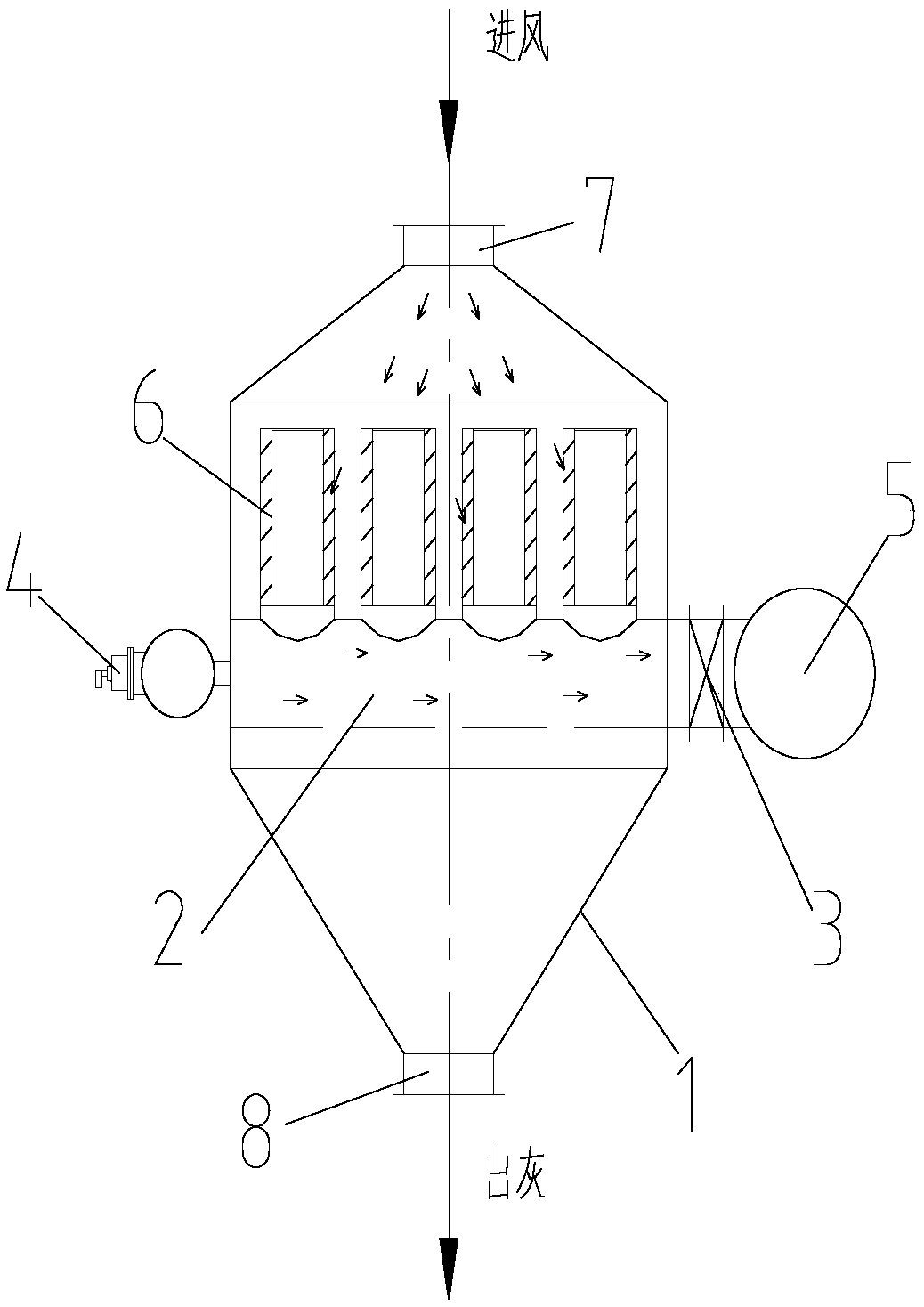
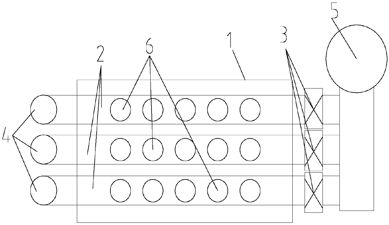
[0021] See attached figure 1 , figure 2 As shown, a kind of air box type blow pipe dust collector in the present embodiment comprises box body 1, and described box body 1 is made up of air inlet box body, filter box body and ash hopper distributed up and down, in the air inlet box The air inlet 7 is arranged on the body, and the ash outlet 8 is arranged below the ash hopper; a group of spray blow pipes 2 (the number of spray blow pipes in this embodiment is three) are arranged in the filter box, and each The upper end face of the blow pipe 2 described above is provided with several flange connections (there are four flange connections in the present embodiment), and a filter cartridge 6 can be vertically installed on each flange connection (if The flange interface is not equipped with a filter cartridge, which can be blocked by installing a cover plate); the two ends of the spray blowpipe 2 all extend to the outside of the casing 1, and each spray blowpipe 2 on the same side...

Embodiment 2

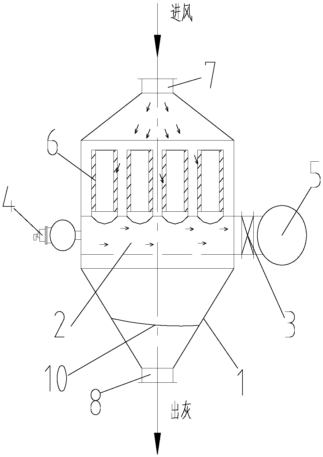
[0025] A kind of air box type blow pipe dust remover among the present embodiment, as image 3 As shown, its structure is substantially the same as that of Embodiment 1, except that a filter screen 10 is arranged below the blowing duct 2, and the edge of the filter screen 10 is fixedly installed on the box body 1.

[0026] Such as Figure 4 (a), Figure 4 A filter screen 10 shown in (b) has a corrugated structure. The wave crest of the filter screen 10 is located in the gap between the two spraying blow pipes 2, and the filter screen 10 in contact with the box body 1 is its wave peak or trough, and the trough of the filter screen 10 is provided with a drain. Dust can be blocked by filter screen 10 like this, avoids that the air-flow of ash outlet 8 place is excessive and influences the deposition of dust in the ash bucket that links to each other with ash outlet. Under normal circumstances, the ash outlet of the dust collector will be connected with the ash bucket for dust ...


PUM


Abstract

The invention discloses a gas box type blowing wind pipe dust removing device, which comprises a box body, wherein the box body comprises a wind inlet box body, a filtering box body and an ash hopper,the wind inlet box body, the filtering box body and the ash hopper are distributed up and down, a wind inlet is formed in the wind inlet box body, an ash outlet is formed below the ash hopper, a group of blowing wind pipes are arranged in the filtering box body, a plurality of flange interfaces are arranged on the upper end surfaces of each blowing wind pipe, a filtering cylinder can be vertically mounted on each flange interface, the two ends of the blowing wind pipe extend out of the box body, pulse valves connected with a gas source are arranged on each blowing wind pipe on the same side of the box body, off-line valves are arranged on each blowing wind pipe on the other side of the box body, the blowing wind pipes on one sides of the off-line valves are communicated with a wind outletgathering pipe, and a fan is arranged on the wind outlet gathering pipe. According to the invention, by increasing the diameter of the blowing wind pipe, the filtering cylinder is directly mounted onthe blowing wind pipe to increase the flow of the gas flow in the blowing wind pipe, so that the back blowing operation of the filtering cylinder is well realized; and the gas box type blowing wind pipe dust removing device is simple in overall structure, convenient to mount and convenient to maintain.

Description

technical field [0001] The invention relates to the field of dust removal equipment, in particular to an air box-type dust collector for spraying blow pipes. Background technique [0002] The filter cartridge dust collector is composed of a filter cartridge as a filter element or a dust collector using pulse injection. The dust-laden gas enters the box through the air inlet, and then passes downward through the filter cartridge, and the dust is collected on the outer surface of the filter cartridge, and the filtered clean air passes through the center of the filter cartridge and is discharged through the air outlet pipe. When the dust accumulates on the surface of the filter cartridge and the resistance increases and reaches the set value, the pulse valve is opened, and the compressed air is directly sprayed into the center of the filter cartridge to remove the dust attached to the outer surface of the filter cartridge, and the dust particles fall into the dust bucket. [...

Claims


Application Information

Patent Timeline
IPC IPC(8): B01D46/00
CPCB01D46/56B01D46/70
Inventor 严学成
Owner 苏州科思瑞得环保科技有限公司
Why Eureka
Try Eureka