Oil duct structure of gas distribution system and gas distribution system

A technology of oil passages and lubricating oil passages, which is applied in the lubrication of valve accessories, engine lubrication, engine components, etc., can solve the problems of less lubricating oil, poor lubrication, and wear of the gas distribution system, so as to improve wear and tear. , to ensure the effect of working accuracy and reliability

Active Publication Date: 2020-03-03
BORGWARD AUTOMOTIVE CHINA CO LTD
View PDF8 Cites 0 Cited by
  • Summary
  • Abstract
  • Description
  • Claims
  • Application Information

AI Technical Summary

Problems solved by technology

In order to avoid the friction between the parts and affect the working accuracy of the system, in the general prior art, the joint surfaces of each part are lubricated by the lubricating oil generated by the rotation of the cam. Since the lubricating oil generated by the rotation of the cam is too dispersed, effective lubricating oil Too little, especially the friction position between the cam and the roller and the friction position between the valve and the rocker arm are also constantly changing, resulting in poor lubrication and serious wear on the joint surfaces of the gas distribution system

Method used


Image

  • Oil duct structure of gas distribution system and gas distribution system
  • Oil duct structure of gas distribution system and gas distribution system
  • Oil duct structure of gas distribution system and gas distribution system

Examples


Embodiment Construction

[0026] Specific embodiments of the present disclosure will be described in detail below in conjunction with the accompanying drawings. It should be understood that the specific embodiments described here are only used to illustrate and explain the present disclosure, and are not intended to limit the present disclosure.

[0027] In this disclosure, unless stated otherwise, the used orientation words such as "up and down" usually refer to the end of the hydraulic tappet close to the rocker arm being up, and the end far away from the rocker arm being down, and "inside and outside". ” are defined for the inside and outside of the profile of each part.

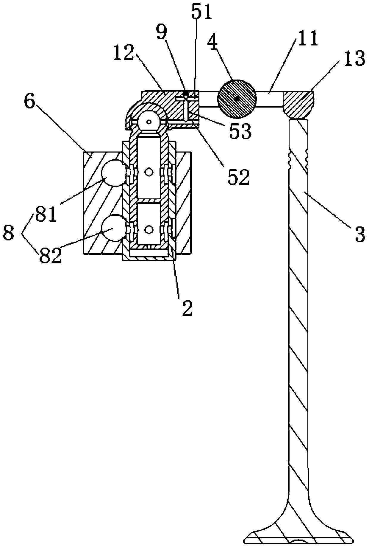
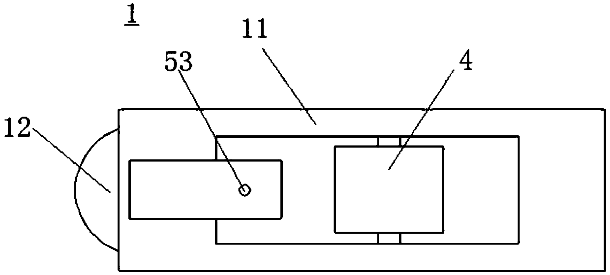
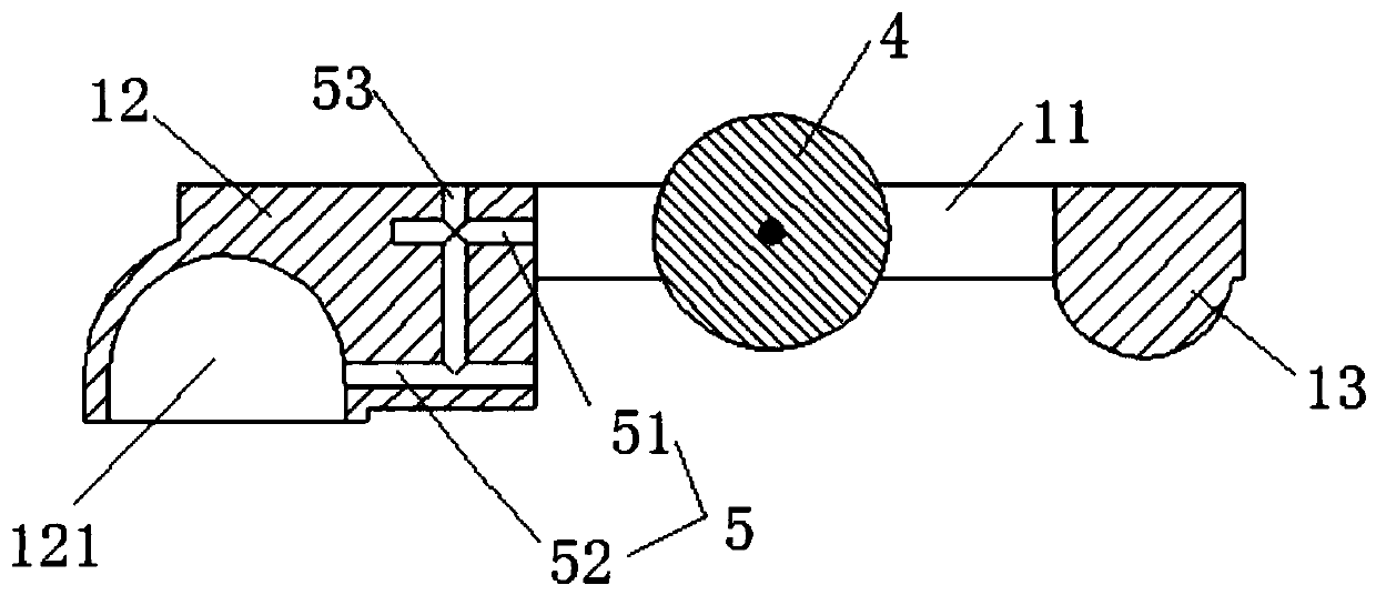
[0028] Such as Figure 1 to Figure 7 As shown, the present disclosure provides an oil channel structure for a gas distribution system. The gas distribution system includes a rocker arm 1, a cam, a hydraulic tappet 2 and a valve 3, and the hydraulic tappet 2 and the valve 3 respectively abut against the rocker arm 1. The two ends...


PUM


Abstract

The invention relates to an oil duct structure of a gas distribution system and the gas distribution system. The gas distribution system comprises a rocker arm, a cam, a hydraulic tappet and a valve,wherein the hydraulic tappet and the valve abut against the two ends of the rocker arm correspondingly, a roller abutting against the cam is movably arranged on the rocker arm, the cam drives the roller to enable the rocker arm to rotate around the hydraulic tappet, the oil duct structure comprises a lubricating oil duct arranged in the rocker arm, wherein the lubricating oil duct comprises a first lubricating oil duct used for lubricating the roller or / and a second lubricating oil duct lubricating the abutment point of the valve and the rocker arm. The lubricating oil duct is mainly used foreffectively lubricating the friction bonding surfaces between the valve and the cam, between the rocker arm and the cam and between the roller and the cam in the gas distribution system, so that the working accuracy and reliability of the whole gas distribution system are ensured.

Description

technical field [0001] The present disclosure relates to the field of engine gas distribution, and in particular, relates to an oil channel structure and the gas distribution system for the gas distribution system. Background technique [0002] The gas distribution system of the engine includes tappets, rocker arms, valves and cams. The rocker arm takes the hydraulic tappet as the fulcrum, presses the cam against the roller of the rocker arm, and drives the rocker arm to rotate around the hydraulic tappet to achieve The low-pressure valve at the other end of the rocker arm makes the valve reciprocate in the valve guide to realize the change of the valve lift. In order to avoid the friction between the parts and affect the working accuracy of the system, in the general prior art, the joint surfaces of each part are lubricated by the lubricating oil generated by the rotation of the cam. Since the lubricating oil generated by the rotation of the cam is too dispersed, effective ...

Claims


Application Information

Patent Timeline
IPC IPC(8): F01M9/10F01L1/18F01L1/245
CPCF01L1/18F01L1/245F01M9/10F01M9/101
Inventor 张文德朱亭诺张志文王照坤
Owner BORGWARD AUTOMOTIVE CHINA CO LTD
Why Eureka
Try Eureka