
Drip irrigation device for agricultural greenhouses

A greenhouse and agricultural technology, applied in the agricultural field, can solve problems such as poor effect, achieve the effect of ensuring the sealing effect and improving the actual use effect

Inactive Publication Date: 2020-03-06
汤槐清
View PDF0 Cites 1 Cited by
  • Summary
  • Abstract
  • Description
  • Claims
  • Application Information

AI Technical Summary

Problems solved by technology

[0004] Based on the technical problem that the actual dropper does not correspond to the position of the plant, resulting in poor effect of actual drip irrigation, the present invention proposes a drip irrigation device for agricultural greenhouses

Method used


Image

  • Drip irrigation device for agricultural greenhouses
  • Drip irrigation device for agricultural greenhouses
  • Drip irrigation device for agricultural greenhouses

Examples


Embodiment 1

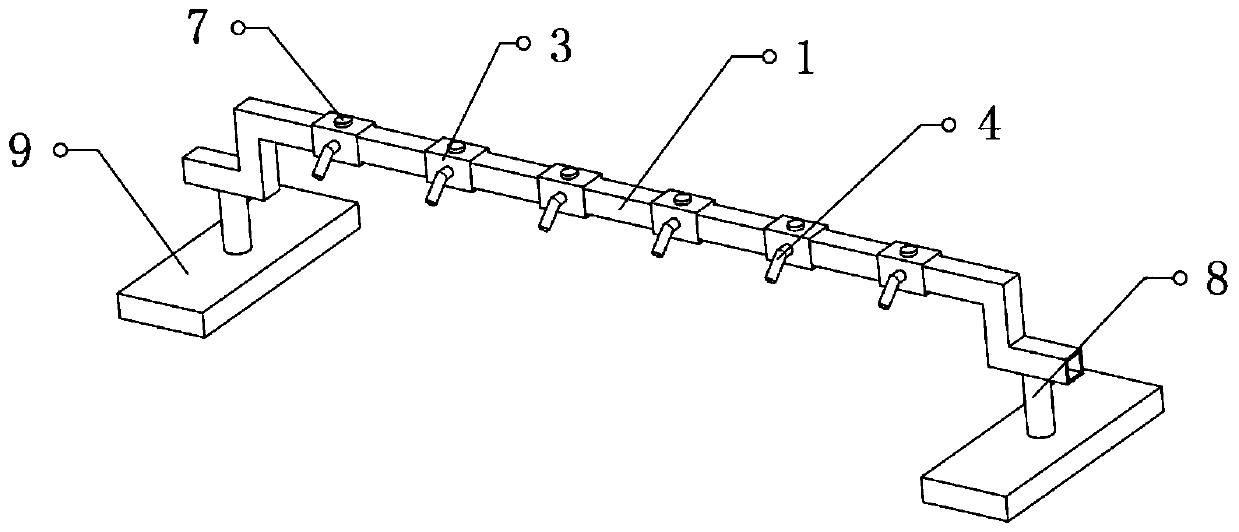
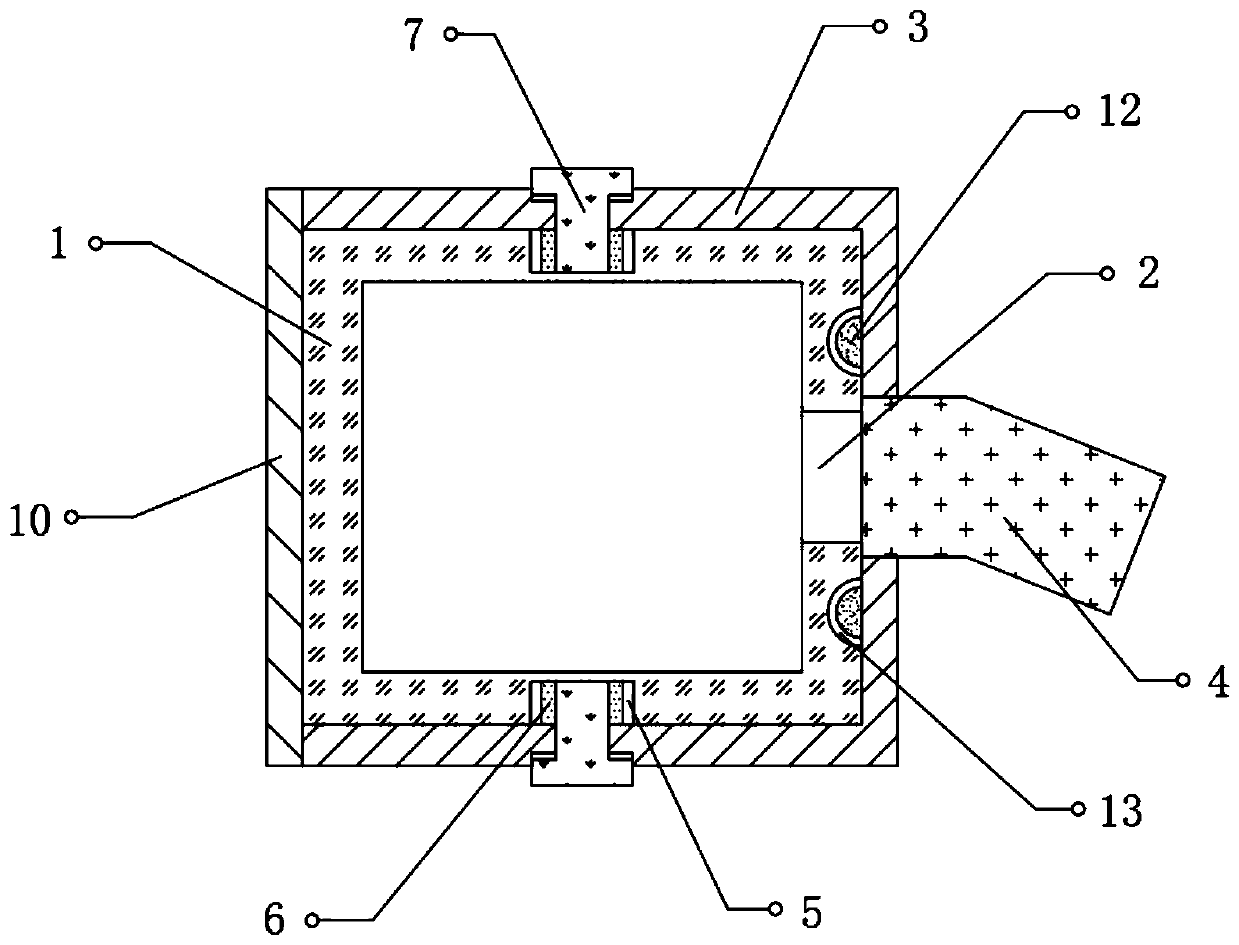
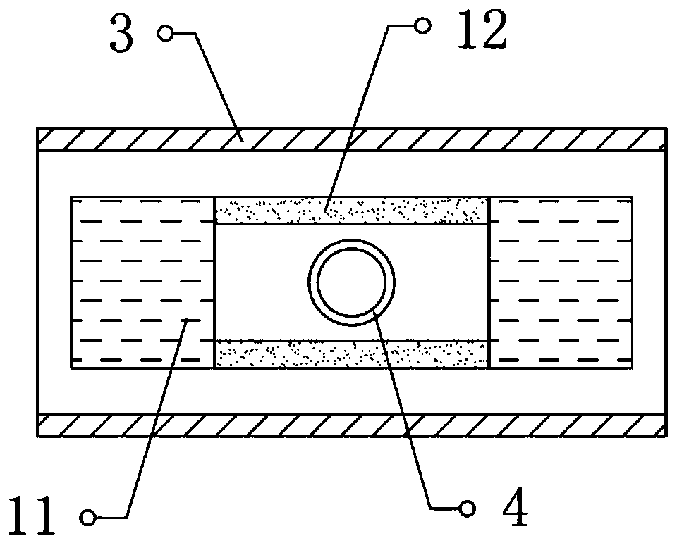
[0026] refer to Figure 1-3 , a drip irrigation device for agricultural greenhouses, comprising a connecting pipe 1, the cross-section of the connecting pipe 1 is set to a square structure, the outer wall of one end of the connecting pipe 1 is provided with a plurality of strip-shaped grooves 2, and the outer wall of the connecting pipe 1 is connected to the through groove 2 The corresponding position is slidingly connected with a connecting ring 3, and the outer wall of one end of the connecting ring 3 is fixed with a dropper 4 communicating with the through groove 2. A flow valve is arranged inside the dropper 4, and a chute is opened on the top and bottom outer walls of the connecting pipe 1. 5, and the position corresponding to the inner wall of the connecting ring 3 and the chute 5 is fixed with a slider 6, the top of the slider 6 is provided with a perforation, and the position corresponding to the outer wall of the connecting ring 3 and the perforation is screwed with a ...

Embodiment 2

[0030] refer to Figure 4-5 , a drip irrigation device for agricultural greenhouses, the support member 8 is set as a connecting member 14 hinged to the bottom of the connecting pipe 1, and the top of the base 9 is provided with an auxiliary groove, and the inner wall of the auxiliary groove is slidably connected with a connecting block 15, and the connecting block 15 Hinged between the top of the top and the bottom end of the connecting piece 14, a through hole is provided on one side of the connecting block 15, and an adjusting rod 16 is rotatably connected between the inner walls on both sides of the auxiliary groove, and the outer wall of the adjusting rod 16 is connected to the inner wall of the through hole. There is a threaded connection between them, and a vertically placed spring 17 is fixedly connected between the bottom of the connecting pipe 1 and the top of the base 9, and the spring 17 is located on the side of the connecting piece 14 close to the connecting pipe ...


PUM


Abstract

The invention belongs to the technical field of agriculture, and particularly relates to a drip irrigation device for agricultural greenhouses. To solve the problem of poor actual drip irrigation effect caused by non-correspondence between actual positions of droppers and plants, the following solution is provided. The drip irrigation device comprises a communicating pipe; the cross section of thecommunicating pipe is set as a square structure, a plurality of strip-shaped through grooves are formed in the outer wall of one end of the communicating pipe, connecting rings are slidably connectedto positions, corresponding to the through grooves, on the outer wall of the communicating pipe, droppers communicated with the through grooves are fixed to the outer walls of one ends of the connecting rings, flow valves are arranged in the droppers, sliding grooves are formed in the outer walls of the top and the bottom of the communicating pipe, sliders are fixed to positions, corresponding tothe sliding grooves, on the inner walls of the connecting rings, and through holes are formed in the tops of the sliders. The drip irrigation device has the advantages that the positions of the droppers can be adjusted through horizontal movement of the connecting rings, fastening bolts are abutted against the sliding grooves to fasten the connecting rings, the positions of the droppers can be adjusted according to the actual positions of the plants, and accordingly, the practical usage effect of the drip irrigation device is improved.

Description

technical field [0001] The invention relates to the field of agricultural technology, in particular to a drip irrigation device for agricultural greenhouses. Background technique [0002] Agriculture is an industry that uses the growth and development laws of animals and plants to obtain products through artificial cultivation. Agriculture belongs to the primary industry. The science that studies agriculture is agronomy. The labor objects of agriculture are living animals and plants, and the products obtained are the animals and plants themselves. , Nowadays, greenhouses are often used in the agricultural production process to grow vegetables. [0003] In the process of planting in greenhouses, watering operations are often required. With the continuous development of science and technology, in the prior art, drip irrigation technology is often used in areas where water is scarce, and the pipes connected to the water source are installed next to the plants. There are multip...

Claims


Application Information

Patent Timeline
Patent Type & Authority Applications(China)
IPC IPC(8): A01G9/14A01G9/24F16J15/06F16L41/08
CPCA01G9/14A01G9/247F16J15/068F16L41/08Y02A40/25
Inventor 汤槐清
Owner 汤槐清
Learn More