
Rotor clutch mechanism

A clutch mechanism and rotor technology, which is applied in electromechanical devices, mechanical energy control, metal processing, etc., can solve the problems that it is difficult to meet the application requirements of multiple occasions, and the state switching of motor equipment cannot be automatically completed.

Pending Publication Date: 2020-03-06
深圳市爱贝科精密工业股份有限公司
View PDF0 Cites 2 Cited by
  • Summary
  • Abstract
  • Description
  • Claims
  • Application Information

AI Technical Summary

Problems solved by technology

[0002] In the existing technology, in many cases, the rotor of the motor equipment needs to perform corresponding actions during operation, but in some occasions, such as when performing turning operations, the rotor needs to be fixed at a specified position. In addition, sometimes the rotor needs to be Rotate with other mechanisms, and in the existing motor equipment, it is usually necessary to lock the rotor with an external locking device, or fix the external power transmission device on the rotor, so that the rotor can transmit power to other mechanisms In the above-mentioned applications, it is necessary to assemble different mechanisms to realize it, which makes the existing motor equipment unable to automatically complete the state switching, and it is difficult to meet the application requirements of multiple occasions.

Method used


Image

  • Rotor clutch mechanism
  • Rotor clutch mechanism
  • Rotor clutch mechanism

Examples


Embodiment 1

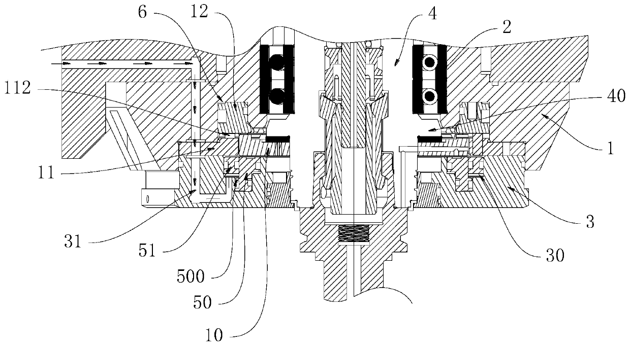
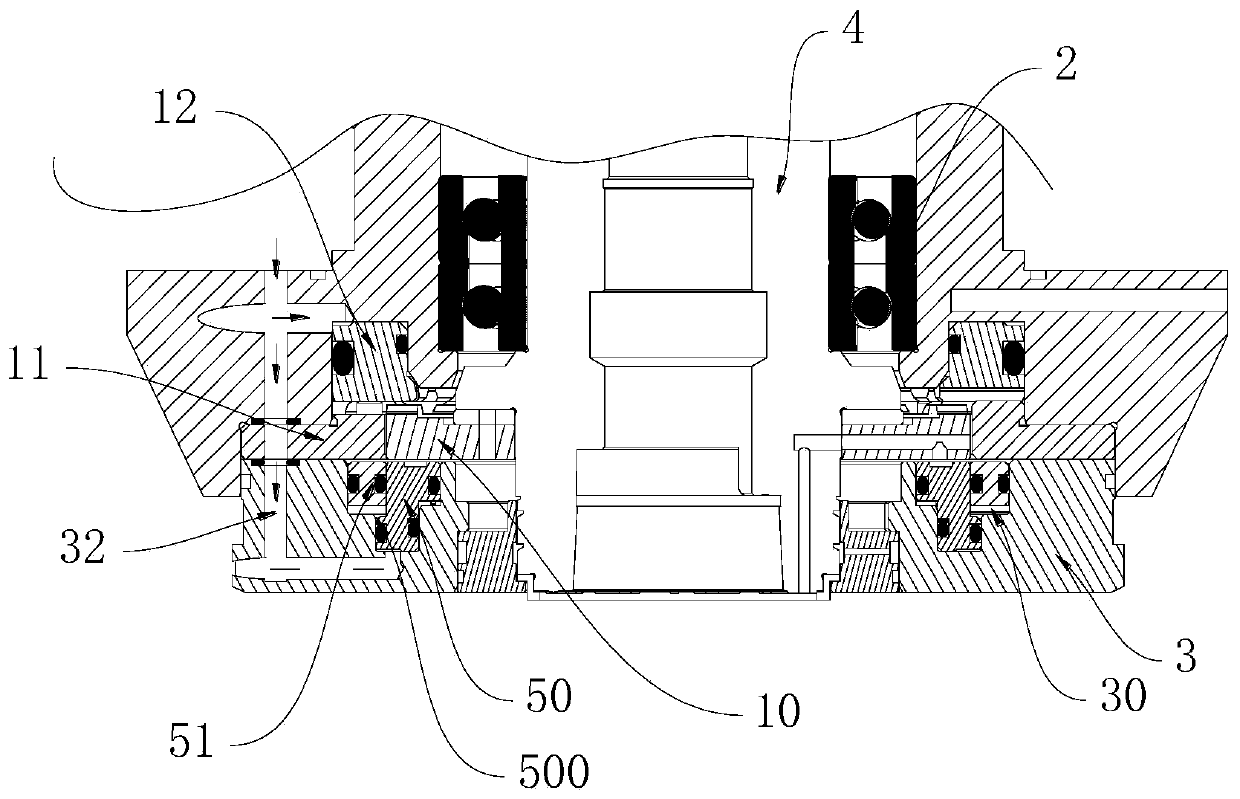
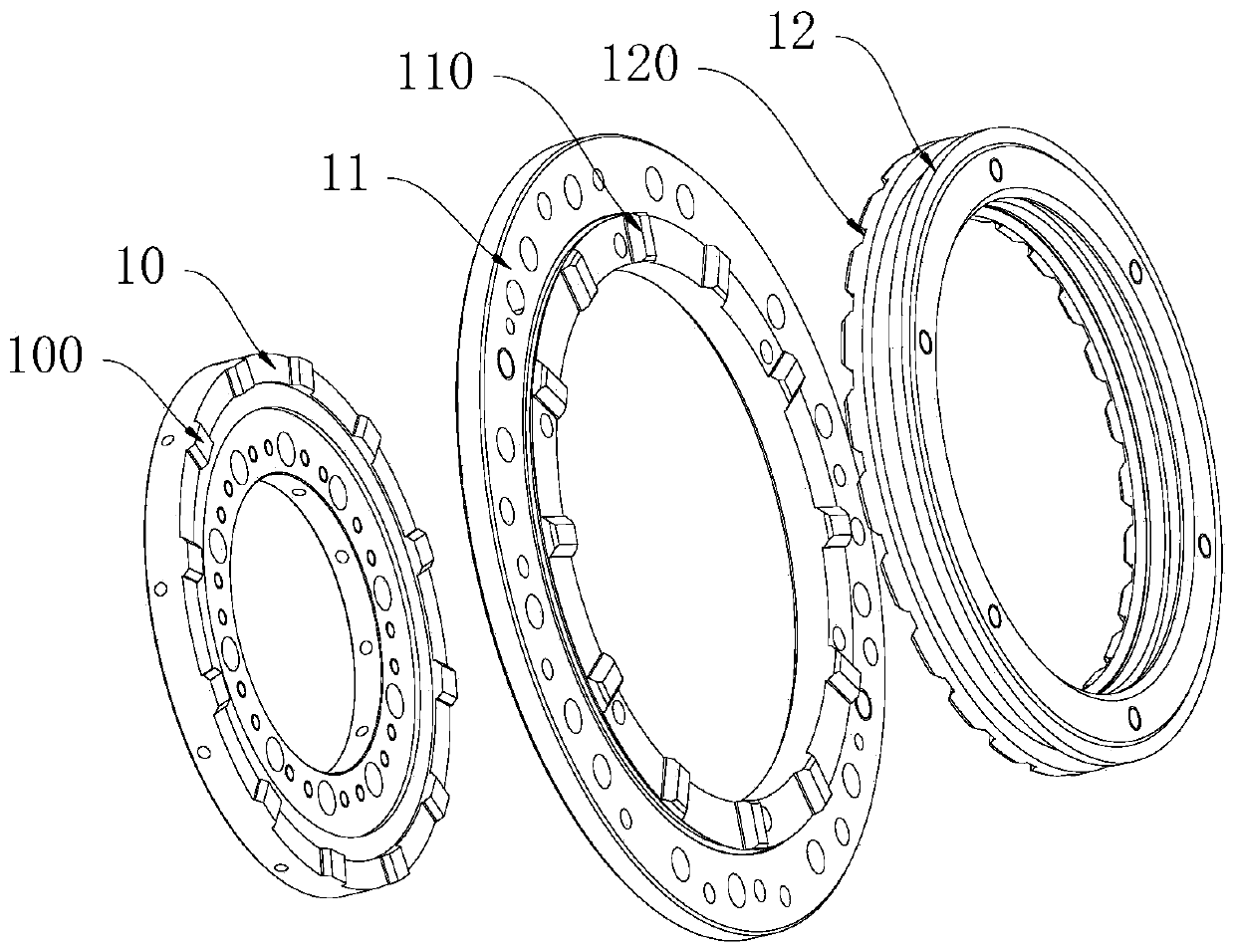
[0018] This embodiment proposes a rotor clutch mechanism, combined with image 3 with Figure 4 As shown, it includes an inner ring disk 10 sleeved and fixed on the rotor 4, an outer ring disk 11 is sleeved on the outer side of the inner ring disk 10, and the inner ring disk 10 can be opposite to the outer ring disk 10. The ring disc 11 rotates, and the rear side of the inner ring disc 10 and the outer ring disc 11 is provided with a rear piston ring 12 capable of sliding back and forth, the rear piston ring 12 surrounds the rotor 4, and the inner ring disc The rear end surface of 10 is formed with a plurality of inner ring protrusions 100, and the plurality of inner ring protrusions 100 are evenly distributed along the circumferential direction of the inner ring disc 10, and the rear end surface of the outer ring disc 11 is formed with a plurality of outer ring protrusions. Block 110, a plurality of outer ring protrusions 110 are evenly distributed along the circumference of...

Embodiment 2

[0032] In practical applications, the spindle is usually used in precision machining and other occasions, and can be used for turning or milling. For turning, it needs the spindle to fix the turning tool at a predetermined position, and use the rotating workpiece to contact the turning tool to complete turning. As far as milling is concerned, it is necessary for the spindle to carry the milling cutter at high speed to complete the milling process. The above two processing methods require different types of spindle structures to be realized, or use an independent clamping device to turn the spindle The rotor is fixed and positioned, but the above method not only has poor automation performance, but also is inconvenient to operate. In addition, the method of fixing the rotor by external force is easy to cause damage to the internal structure of the spindle, which in turn affects the precision of the spindle, which is difficult to meet the application requirements.

[0033] This e...


PUM


Abstract

The invention discloses a rotor clutch mechanism. The rotor clutch mechanism comprises an inner ring disc which is arranged on a rotor in a sleeving mode and fixed to the rotor, wherein the outer sideof the inner ring disc is sleeved with an outer ring disc; a rear piston ring capable of sliding front and back is arranged on the rear side of the inner ring disc and the rear side of the outer ringdisc and surrounds the rotor; a plurality of inner ring protruding blocks are formed on the rear end face of the inner ring disc; a plurality of outer ring protruding blocks are formed on the rear end face of the outer ring disc; a plurality of piston clamping openings are formed in the front end face of the rear piston ring; the inner ring protruding blocks and the outer ring protruding blocks are aligned with the piston clamping openings correspondingly; when the rear piston ring slides forwards, the inner ring protruding blocks and the outer ring protruding blocks are inserted into the piston clamping openings correspondingly; and when the rear piston ring slides backwards, the rear piston ring is separated from the inner ring disc and the outer ring disc. According to the rotor clutchmechanism, the rotor can be in various working states such as independent rotation or locking or outward power transmission only by controlling the rear piston ring to slide forwards or backwards, and then the machining requirements in various occasions are met.

Description

technical field [0001] The invention relates to motor equipment, in particular to a rotor clutch mechanism. Background technique [0002] In the existing technology, in many cases, the rotor of the motor equipment needs to perform corresponding actions during operation, but in some occasions, such as when performing turning operations, the rotor needs to be fixed at a specified position. In addition, sometimes the rotor needs to be Rotate with other mechanisms, and in the existing motor equipment, it is usually necessary to lock the rotor with an external locking device, or fix the external power transmission device on the rotor, so that the rotor can transmit power to other mechanisms Among them, in the above-mentioned applications, different mechanisms need to be assembled to realize it. As a result, the existing motor equipment cannot automatically complete the state switching, and it is difficult to meet the application requirements of multiple occasions. Contents of t...

Claims


Application Information

Patent Timeline
IPC IPC(8): B23Q5/54B23Q5/00H02K7/10
CPCB23Q5/00B23Q5/54H02K7/10
Inventor 农乃昌
Owner 深圳市爱贝科精密工业股份有限公司
Learn More