Aeration device for treatment of environmental engineering sewage

A technology for sewage treatment and environmental engineering, applied in biological water/sewage treatment, water aeration, water/sludge/sewage treatment, etc. The effect of aeration efficiency

Inactive Publication Date: 2020-03-06
李郅恺
View PDF0 Cites 0 Cited by
  • Summary
  • Abstract
  • Description
  • Claims
  • Application Information

AI Technical Summary

Problems solved by technology

[0003] During the aeration process of the existing aeration device, the mixing of sewage and air bubbles is not uniform enough, and the aeration efficiency is low

Method used


Image

  • Aeration device for treatment of environmental engineering sewage
  • Aeration device for treatment of environmental engineering sewage
  • Aeration device for treatment of environmental engineering sewage

Examples


Embodiment 1

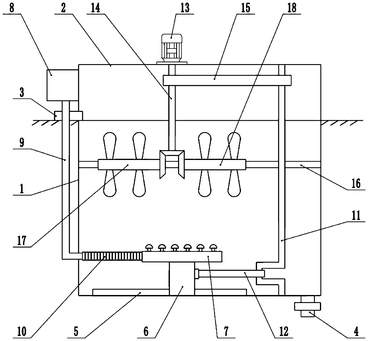
[0022] See Figure 1-3 In the embodiment of the present invention, an aeration device for environmental engineering sewage treatment includes a tank body 1, a water inlet pipe 3, a drain pipe 4, an aeration plate 7 and a blower 8. The top of the pool body 1 is fixedly connected with a fixing frame 2 A water inlet pipe 3 is installed above the side wall of the pool body 1, sewage is injected into the pool body 1 through the water inlet pipe 3, a drain pipe 4 is installed at the bottom of the pool body 1, and a valve is installed on the drain pipe 4, and the treated sewage passes through The drain pipe 4 is discharged. A slide rail 5 is installed at the bottom of the pool body 1, and a slide block 6 is slidably connected to the slide rail 5. The slide block 6 can slide left and right along the slide rail 5, and the upper surface of the slide block 6 is fixedly connected with aeration Disk 7, aeration disk 7 is hollow, aeration heads are distributed on the upper surface of the aer...

Embodiment 2

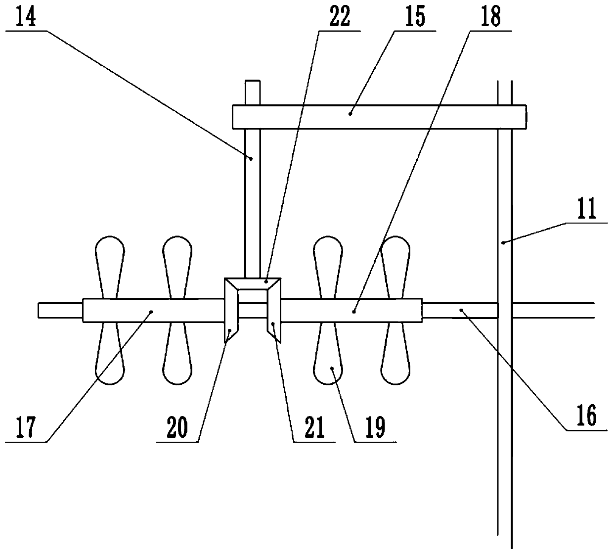
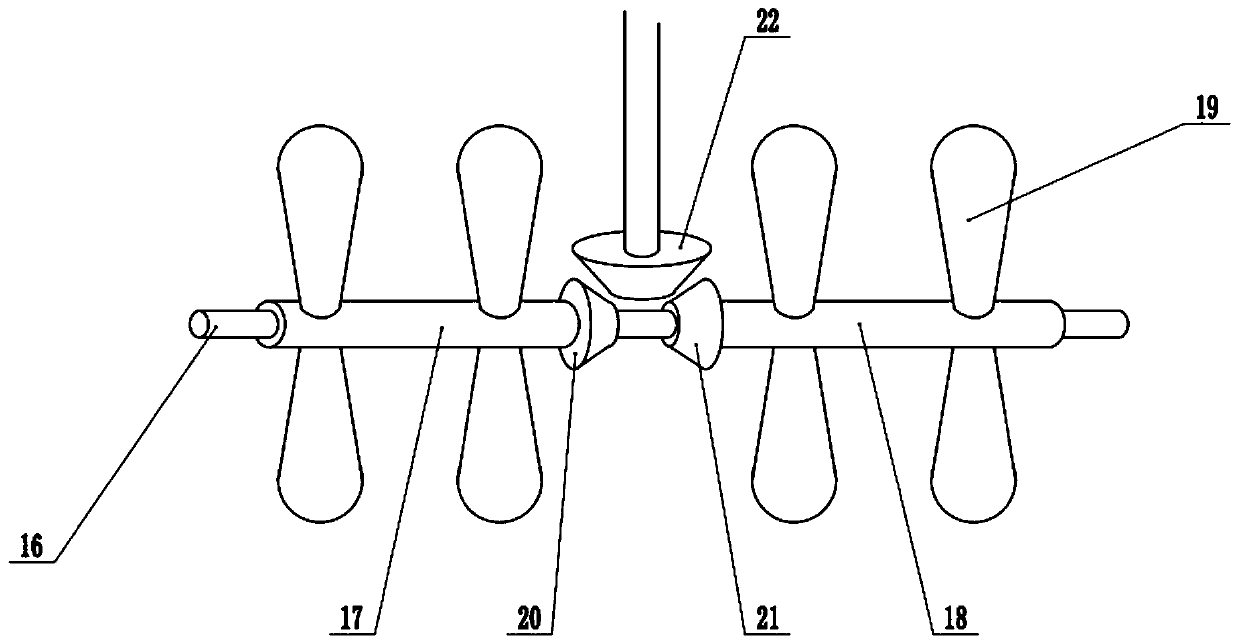
[0024] On the basis of embodiment 1, the right end of the left sleeve 17 is sleeved with a left bevel gear 20, the left end of the right sleeve 18 is sleeved with a right bevel gear 21, the lower end of the drive shaft 14 is sleeved with an upper bevel gear 22, and the left bevel gear The gear 20 and the right bevel gear 21 respectively mesh with the upper bevel gear 22. When the motor 13 is running, the drive shaft 14 is driven to rotate, which in turn drives the left sleeve 17 and the right sleeve 18 to rotate synchronously, and the left sleeve 17 and the right sleeve 18 The aeration blade 19 is used to agitate the sewage. Because the left sleeve 17 and the right sleeve 18 rotate in opposite directions, the uncertainty of sewage disturbance during the mixing process is increased, so that the sewage and bubbles are mixed more evenly and further improved Aeration efficiency.

Embodiment 1、 Embodiment 2

[0025] Combining Embodiment 1 and Embodiment 2, the working principle of the present invention is: sewage is injected into the tank body 1 through the water inlet pipe 3, so that the sewage floods the aeration blades 19, starts the blower 8, and uses the blower 8 to transport air to the aeration tray 7. , And then discharged into the sewage through the aeration head on the aeration plate 7 to aerate the bottom sewage. At the same time, the motor 13 is started. When the motor 13 is running, the drive shaft 14 is driven to rotate, and the crankshaft 11 is driven to rotate synchronously through the transmission belt 15. When 11 rotates, the slider 6 is driven to move left and right along the slide rail 5 through the connecting rod 12, thereby driving the aeration plate 7 to move left and right, so that bubbles are discharged into the sewage more evenly, and the aeration efficiency is improved. Moreover, when the motor 13 is running , Drives the drive shaft 14 to rotate, and then dr...


PUM


Abstract

The invention relates to the field of environmental protection equipment, particularly to an aeration device for treatment of environmental engineering sewage. The device comprises a tank body, a water inlet pipe, a drain pipe, an aeration disc and a blower, wherein the top of the tank body is fixedly connected with a fixed frame; a slide rail is mounted at the bottom of the tank body; a sliding block is slidably connected to the slide rail; the upper surface of the sliding block is fixedly connected with the aeration disc; the side wall of the fixed frame is fixedly connected with the blower;a crankshaft is mounted in the tank body; a connecting rod sleeves the shaft neck of the crankshaft; the upper surface of the fixed frame is fixedly connected with a motor; the shaft extension end ofthe motor is fixedly connected with a driving shaft; a fixed rod is mounted in the tank body; and the fixed rod is sleeved with a left sleeve and a right sleeve. The blower is used for conveying airto the aeration disc for aeration of bottom-layer sewage; the motor is used for driving the aeration disc to move left and right, so bubbles are discharged into the sewage more uniformly; and during aeration operation, the left sleeve and the right sleeve rotate synchronously, and aeration blades stir the sewage, so the sewage and the bubbles are mixed more uniformly.

Description

Technical field [0001] The invention relates to the field of environmental protection equipment, and more specifically, to an aeration device for environmental engineering sewage treatment. Background technique [0002] The aeration tank is a biochemical reactor designed by people according to the characteristics of microorganisms. The degradation degree of organic pollutants mainly depends on the aeration reaction conditions designed by people. The aeration tank uses the activated sludge method for sewage treatment, and a certain retention time of sewage is provided in the tank to meet the oxygen content required by aerobic microorganisms and the mixing conditions of full contact between sewage and activated sludge. The aeration tank is mainly composed of three parts: tank body, aeration system and water inlet and outlet. The pool body is generally made of reinforced concrete, and the plane shapes are rectangular, square and round. [0003] In the aeration process of the existin...

Claims


Application Information

Patent Timeline
Patent Type & Authority Applications(China)
IPC IPC(8): C02F7/00C02F3/12
CPCC02F3/12C02F7/00Y02W10/10
Inventor 李郅恺
Owner 李郅恺
Why Eureka
Try Eureka