Gas well production liquid storage device with multi-stage defoaming function and use method

A technology of storage device and defoaming device, which is applied in the valve device of wellbore/well, earthwork drilling, flushing wellbore, etc. Utilization, reduce the time used, ensure the effect of continuous normal work

Active Publication Date: 2020-03-06
CHINA PETROLEUM & CHEM CORP +1
View PDF11 Cites 0 Cited by
  • Summary
  • Abstract
  • Description
  • Claims
  • Application Information

AI Technical Summary

Problems solved by technology

[0005] The purpose of the present invention is to solve the problem that the existing gas well production liquid does not undergo defoaming treatment when it is input into the liquid storage tank, resulting in a low volume utilization rate of the liquid storage tank, and causing the hidden danger of foam overflow in the liquid storage tank, which affects the gas well. To solve the technical problems of production, a gas well production liquid storage device with multi-stage defoaming function and its use method are provided

Method used


Image

  • Gas well production liquid storage device with multi-stage defoaming function and use method
  • Gas well production liquid storage device with multi-stage defoaming function and use method
  • Gas well production liquid storage device with multi-stage defoaming function and use method

Examples


Embodiment 1

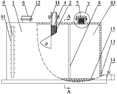
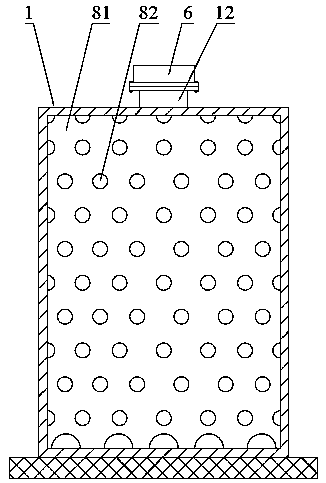
[0040] Such as Figure 1-3 As shown, the gas well production liquid storage device with multi-stage defoaming function includes a liquid storage tank 1, and the liquid storage tank 1 is provided with a liquid inlet 11 and a liquid discharge port 13, and the liquid inlet 11 is connected to the liquid through a pipeline. The oil pipes and / or casings of the gas tree are connected, the liquid discharge port 13 is provided with a control valve 14 that can be opened and / or closed, the liquid inlet port 11 is arranged on the top of the liquid storage tank 1, and the liquid discharge port 14 is arranged on the bottom edge of one side of the liquid storage tank 1, the bottom of the liquid storage tank 1 is also provided with a base 15, the liquid storage tank 1 is detachably connected with the base 15, and the liquid storage tank 1 is provided with At least one defoaming device, the defoaming device includes a liquid inlet defoaming mechanism 2, the liquid inlet defoaming mechanism 2 i...

Embodiment 2

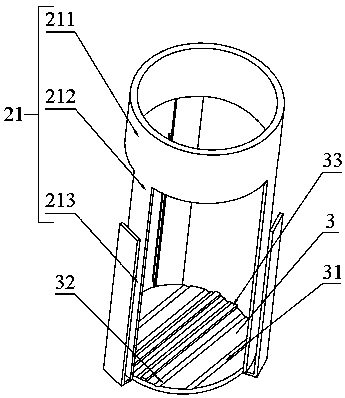
[0045] Such as figure 1 and image 3 As shown, the structure of the gas well liquid storage device with multi-stage defoaming function in this embodiment is the same as that of Embodiment 1, the difference is that the deflector 3 is provided with a buffer mechanism for separating foam For the gas and liquid in the buffer mechanism, the buffer mechanism includes a guide groove 31 and / or a guide rib 32 and / or an adsorption mechanism 33 to form a second-stage defoaming treatment structure.

[0046] The gas well production liquid storage device with multi-stage defoaming function in this embodiment, by setting the flow guide groove 31 on the deflector 3, is beneficial to make the gas well production fluid entering from the liquid inlet hit the deflector 3 Concentrate the flow along the diversion grooves 31 to increase the liquid flow in each diversion groove 31, thereby reducing the foam in the gas well production fluid, so that the defoaming effect is better.

[0047] More pref...

Embodiment 3

[0050] Such as Figure 1-4 As shown, the gas well production liquid storage device with multi-stage defoaming function of this embodiment has the same structure as that of Embodiment 2, the difference is that the defoaming device also includes a filter defoaming mechanism 4, and the filter defoaming mechanism 4 Including at least one layer of defoaming net 41, the bracket 21 is provided with a clamping groove 213 for clamping the defoaming net 41, and the defoaming net 41 is detachably arranged in the clamping groove 213. A liquid-inlet defoaming space 42 is formed between the flow plate 3 and the liquid inlet 11, forming a third-stage defoaming treatment structure.

[0051] In the gas well production liquid storage device with multi-stage defoaming function in this embodiment, it is preferable that the connecting strip 212 on the bracket 21 is folded outward to form a clamping groove 213 for clamping the defoaming net 41, and the defoaming net 41 is made of steel wire filter...


PUM


Abstract

The invention relates to an auxiliary device for a natural gas well mining process, in particular to a gas well production liquid storage device with a multi-stage defoaming function and a use method.The storage device comprises a liquid storage tank, wherein a liquid inlet and a liquid outlet are formed in the liquid storage tank, at least one defoaming device is arranged in the liquid storage tank, so that the gas well production liquid output by an oil pipe and/or a sleeve of a gas production tree is subjected to defoaming treatment in the liquid storage tank, the bubble content in the gaswell production liquid in the liquid storage tank is reduced, the volume utilization rate of the liquid storage tank is improved, and meanwhile, the foam overflow in the liquid inlet process due to the fact that foams of the gas well production liquid occupies a larger space in the liquid storage tank is avoided. According to the the storage device, the liquid storage tank is connected with an interface of the oil pipe and/or an interface of the sleeve of the gas production tree before the bubble discharge process, after a control valve of the gas production tree is opened, a liquid flow channel from a gas well to the liquid storage tank is formed, the gas well production liquid enters the liquid storage tank from the gas well passing through the gas production tree for storage, and operation is simple.

Description

technical field [0001] The invention relates to an auxiliary device for natural gas well exploitation technology, in particular to a gas well production fluid storage device with multi-stage defoaming function and a use method. Background technique [0002] In the process of natural gas extraction, due to the high pressure of the geological formation, water is gasified under high pressure, and is generally exported from the wellhead of the gas production well together with the natural gas. The pressure gradually decreases, and the gaseous water gas is liquefied into liquid water, and liquid accumulation is formed at the bottom of the natural gas well, which affects the normal output of natural gas. After being in contact with the foam discharge medium, a large amount of low-density foam is generated by the agitation of the natural gas flow at the bottom of the well, and is carried from the bottom of the well to the surface with the air flow to achieve the purpose of clearing...

Claims


Application Information

Patent Timeline
Patent Type & Authority Applications(China)
IPC IPC(8): E21B43/16E21B34/02E21B21/06
CPCE21B43/166E21B34/02E21B21/063
Inventor 任基文薛洪刚闭其云张小军黎昌波黄焕全何海林杜云李峰许鑫朱敏黄学琴刘霞肖雄雷有程邱文秀毛锐陆元高伍益呈林晓艺
Owner CHINA PETROLEUM & CHEM CORP
Why Eureka
Try Eureka