
Flow Separator And Flow Separator Method

a flow separator and flow separator technology, applied in the field of flow separators, can solve the problems of insufficient or reliable separation of liquids at relatively high liquid flow rates of devices, and achieve the effect of reducing the average flow velocity and increasing the accuracy of subsequent measurements

Inactive Publication Date: 2008-07-03
SCHLUMBERGER TECH CORP
View PDF15 Cites 4 Cited by
  • Summary
  • Abstract
  • Description
  • Claims
  • Application Information

AI Technical Summary

Benefits of technology

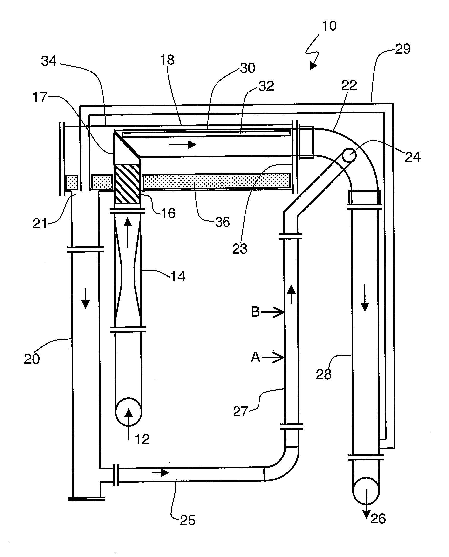
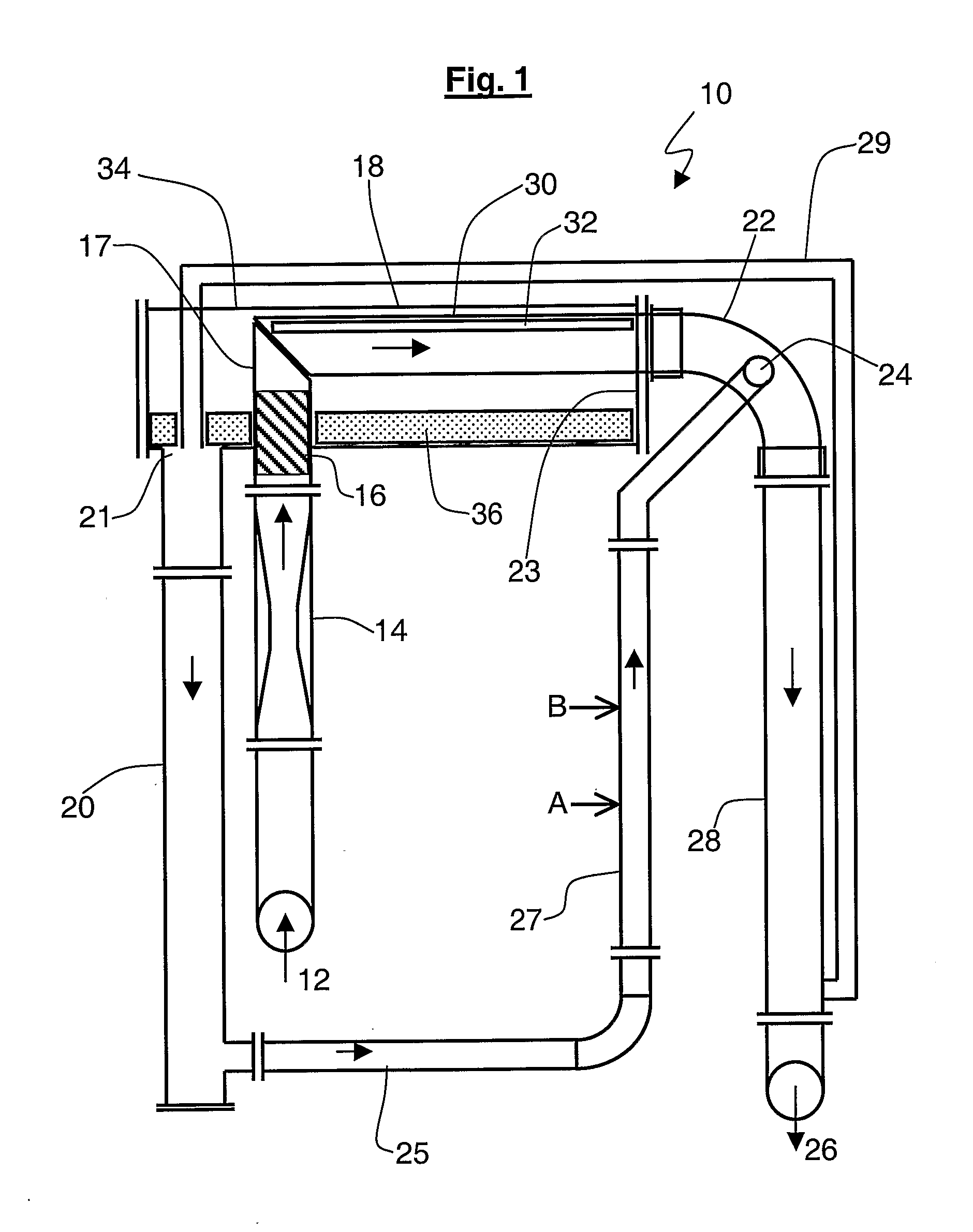
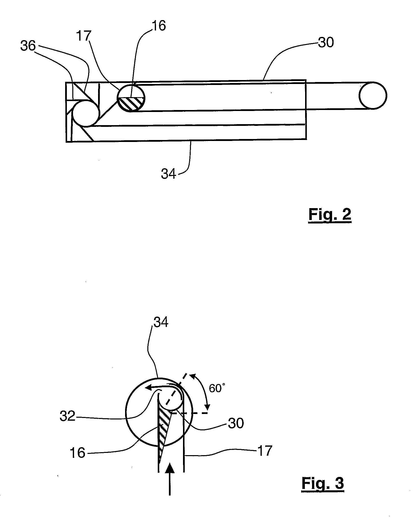
[0019]Preferably, the inner surface of the separation chamber provides a smooth curved path for the swirling liquid to the extraction aperture. This helps to improve the separation efficiency of the separator. Typically, the inner surface of the separation chamber is at least partly cylindrical. This allows the angular velocity of the swirling liquid to be substantially uniform around the separation chamber, again improving the separation efficiency.
[0033]Preferably, the apparatus includes measurement means for measuring properties of the separated liquid. The measurement means may include a volumetric flow measurement device and / or a densitometer and / or a water-liquid ratio meter. Preferably, these are located to measure the liquid in the second arm of the U-tube. This is preferred because at this location, the liquid should be as free from gas bubbles as possible. However, the measurement means may also be located at the inter-arm section of the U-tube, as the liquid here should also be relatively free from gas bubbles. Reducing the bubble content of the liquid for these measurements typically increases the accuracy of the measurements.

Problems solved by technology

In particular, the device may not provide adequate or reliable separation at relatively high liquid flow rates.

Method used


Image

  • Flow Separator And Flow Separator Method
  • Flow Separator And Flow Separator Method
  • Flow Separator And Flow Separator Method

Examples


Embodiment Construction

[0079]Before looking at the embodiments of the invention in detail, the technical problems to be addressed by the embodiments will first be looked at in more detail.

[0080]The limitations of the abovementioned Schlumberger VenturiX™ system have been investigated by the present inventors and quantified using a 52 mm Schlumberger PhaseWatcher™ at a GVF of 90% or greater up to 100% using oil and nitrogen flows at line pressures of between 15 and 60 bara (i.e. between 1.5 and 6.0 MPa absolute). The results show that for GVF3 / h (300 bpd). It is intended that the preferred embodiments of the invention will give improved accuracy results for GVF of 97% and above.

[0081]Looking at the error budget for the Schlumberger VenturiX™ model, the model predicts the liquid and gas volumetric flow rates from the GVF (derived from the nuclear gas hold up and a Slip Law) and the total flow rate (derived from the differential pressure across the Venturi and the nuclear mixture density).

[0082]The wlr is co...


PUM

PropertyMeasurementUnit
angleaaaaaaaaaa
angleaaaaaaaaaa
pressuresaaaaaaaaaa

Abstract

Disclosed is a flow separator, typically for use in separating liquid from gas in a flowing mixture of liquid and gas, e.g. water, oil and gas in a hydrocarbon well production fluid pipeline, the separator having a swirl generator disposed at the inlet to a cylindrical separation chamber and the separation chamber having an elongate liquid extraction slot formed along its wall, such that in operation the swirling flow centrifugally pushes the liquid towards the wall of the separation chamber to exit the separation chamber through the extraction slot into a collection chamber which may allow the return of the extracted liquid back into the main flow using a U-shaped tube.

Description

BACKGROUND TO THE INVENTION[0001]1. Field of the Invention[0002]The present invention relates to a flow separator for separating liquid from a flowing mixture of liquid and gas. The invention also relates to a method for such separation. The invention is of interest, for example, in separation of liquid from gas for the purposes of measurement in flows of hydrocarbon well production fluid. The separator may be used as part of a system to measure the gas, oil and water flow rates of a multiphase flowing mixture. These can be derived, for example, from a Venturi pressure difference measurement, a total liquid flow rate measurement and a water liquid ratio measurement.[0003]2. Related Art[0004]The determination of gas and liquid flow rates in gas-liquid mixtures are important measurements in the oil and gas industry.[0005]The gas volume fraction (GVF) is defined as the gas volumetric flow rate divided by the total volumetric flow rate of the gas-liquid mixture. It is possible to define...

Claims


Application Information

Patent Timeline
Patent Type & Authority Applications(United States)
IPC IPC(8): B01D37/00B01D35/02B01D45/14
CPCB01D45/14B01D45/16G01F1/74
Inventor ATKINSON, IANODDIE, GARYSCOTT, DAVID
Owner SCHLUMBERGER TECH CORP
Learn More