
Thermostatic valve, control method thereof and water heater with the same

A control method and thermostatic valve technology, applied in fluid heaters, lighting and heating equipment, valve operation/release devices, etc., can solve the problems of inability to achieve timely change adjustment, long adjustment time, and low degree of intelligence, and achieve Improved user experience, short adjustment time, and high adjustment accuracy

Pending Publication Date: 2020-03-06
GUANGDONG MACRO GAS APPLIANCE
View PDF0 Cites 9 Cited by
  • Summary
  • Abstract
  • Description
  • Claims
  • Application Information

AI Technical Summary

Problems solved by technology

The mechanical thermostatic valve uses the thermal expansion and contraction principle of the temperature-sensing material to change the flow rate of hot and cold water to reach the water at the set temperature. The temperature-sensing material is easily affected by changes in the external environment, and due to the long reaction time required , high temperature burns are prone to occur during the adjustment process, and timely change and adjustment cannot be achieved, and the degree of intelligence is low
Compared with the following, the electronic thermostatic valve can realize intelligent adjustment. The existing electronic thermostatic valve generally has two control methods. One is to compare the current mixed water temperature with the set temperature, and then directly adjust to the required temperature. , this method takes a long time to adjust; the other is to use the energy conservation relationship between temperature rise and temperature drop to determine the adjustment position, which is easily affected by external changes in the environment, and cannot be adjusted to the required temperature in time, and the overall adjustment time is also longer.
Therefore, the current thermostatic valve generally has the defects of long adjustment time and slow response. In view of this, those skilled in the art need to make further improvements to the thermostatic valve.

Method used


Image

  • Thermostatic valve, control method thereof and water heater with the same
  • Thermostatic valve, control method thereof and water heater with the same

Examples


Embodiment Construction

[0023] This part will describe the specific embodiment of the present invention in detail, and the preferred embodiment of the present invention is shown in the accompanying drawings. Each technical feature and overall technical solution of the invention, but it should not be understood as a limitation on the protection scope of the present invention.

[0024] In the description of the present invention, unless otherwise clearly defined, terms such as setting and connecting should be understood in a broad sense, and those skilled in the art can reasonably determine the specific meanings of the above terms in the present invention in combination with the specific content of the technical solution.

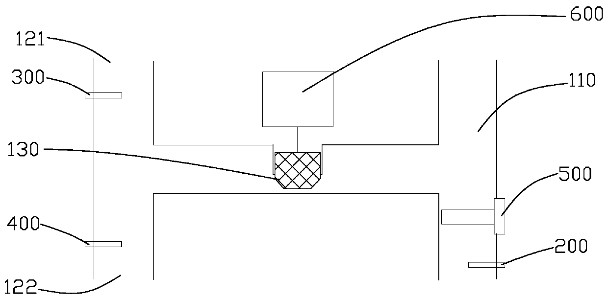
[0025] refer to Figure 1 ~ Figure 2 , taking the thermostatic valve used in the water heater as an example, the thermostatic valve of the present invention makes the following embodiments:

[0026] Including the valve body 100, the valve body 100 is provided with an inner cavity, ...


PUM


Abstract

The invention discloses a thermostatic valve, a control method thereof and a water heater with the same. The thermostatic valve comprises a valve body, an inner cavity, a cold water channel, a hot water channel and a water outlet, wherein the inner cavity comprises a cold water cavity, a hot water cavity and a mixed water cavity; the cold water channel comprises a cold water inlet, a first cold water outlet and a second cold water outlet; the first cold water outlet is in communication with the cold water cavity; the hot water channel comprises a hot water inlet and a hot water outlet; the hotwater inlet is in communication with the second cold water outlet; the hot water outlet is in communication with the hot water cavity; one end of the mixed water cavity is in communication with the cold water cavity and the hot water cavity; the other end of the mixed water cavity is in communication with the water outlet; a valve core is arranged between the first cold water outlet and the second cold water outlet; a stepper motor is connected to the valve core; and the controller is used for receiving the signal feedback of a first temperature sensor, a second temperature sensor, a third temperature sensor and a water flow sensor, thereby sending a control instruction to the stepper motor. The thermostatic valve is short in adjustment time, improves the user experience, and can be applied to the water heater.

Description

technical field [0001] The invention relates to the technical field of thermostatic valves, in particular to a thermostatic valve, a control method thereof and a water heater with the same. Background technique [0002] The thermostatic valve can realize the constant outlet water temperature of the water heater. At present, the thermostatic valves on the market are roughly divided into mechanical thermostatic valves and electronic thermostatic valves. The mechanical thermostatic valve uses the thermal expansion and contraction principle of the temperature-sensing material to change the flow rate of hot and cold water to reach the water at the set temperature. The temperature-sensing material is easily affected by changes in the external environment, and due to the long reaction time required , It is easy to cause high temperature burns during the adjustment process, it cannot achieve timely change adjustment, and the degree of intelligence is low. Compared with the followin...

Claims


Application Information

Patent Timeline
IPC IPC(8): F16K11/02F16K31/04F24H9/20
CPCF16K11/02F16K31/042F24H9/2007
Inventor 艾穗江蒲俊程邓海燕徐扬
Owner GUANGDONG MACRO GAS APPLIANCE
Features
  • Generate Ideas
  • Intellectual Property
  • Life Sciences
  • Materials
  • Tech Scout
  • Unparalleled Data Quality
  • Higher Quality Content
  • 60% Fewer Hallucinations
Learn More