
Rock sample axial extensometer

A rock sample and extensometer technology, applied in the field of rock mechanics test, can solve the problems of long time for sample installation, inability to install axial extensometer, poor matching applicability of extensometer, etc., to achieve perfect accuracy and save scientific research. The effect of shortening time and installation time

Pending Publication Date: 2020-03-06
HUAQIAO UNIVERSITY
View PDF0 Cites 0 Cited by
  • Summary
  • Abstract
  • Description
  • Claims
  • Application Information

AI Technical Summary

Problems solved by technology

[0003] Nowadays, with the continuous improvement and development of experimental methods and experimental equipment, there are several significant problems in the traditional axial extensometer whose upper and lower rings are integral rings: (1) The installation of the sample takes a long time, and the installation process is cumbersome and needs to be repeated. Align the upper and lower rings and adjust the levelness of the upper and lower rings; (2) and the matching applicability of the integral ring extensometer is poor. If a new type of indenter needs to be installed on the sample, the position of the indenter may be larger than the diameter of the upper and lower rings of the extensometer, resulting in The axial extensometer cannot be installed; (3) When installing the upper ring of the extensometer, due to the existence of alignment problems, it often occurs that when the sensor hole is aligned, the copper rod of the extensometer is bent and the sensor of the lower ring is damaged, and in the When adjusting the initial position of the lower magnetic core of the copper rod, the initial position setting is not very accurate due to the coordination problem between the left and right hands

Method used


Image

  • Rock sample axial extensometer
  • Rock sample axial extensometer
  • Rock sample axial extensometer

Examples


Embodiment Construction

[0023] The present invention will be further described below in conjunction with the accompanying drawings and specific embodiments.

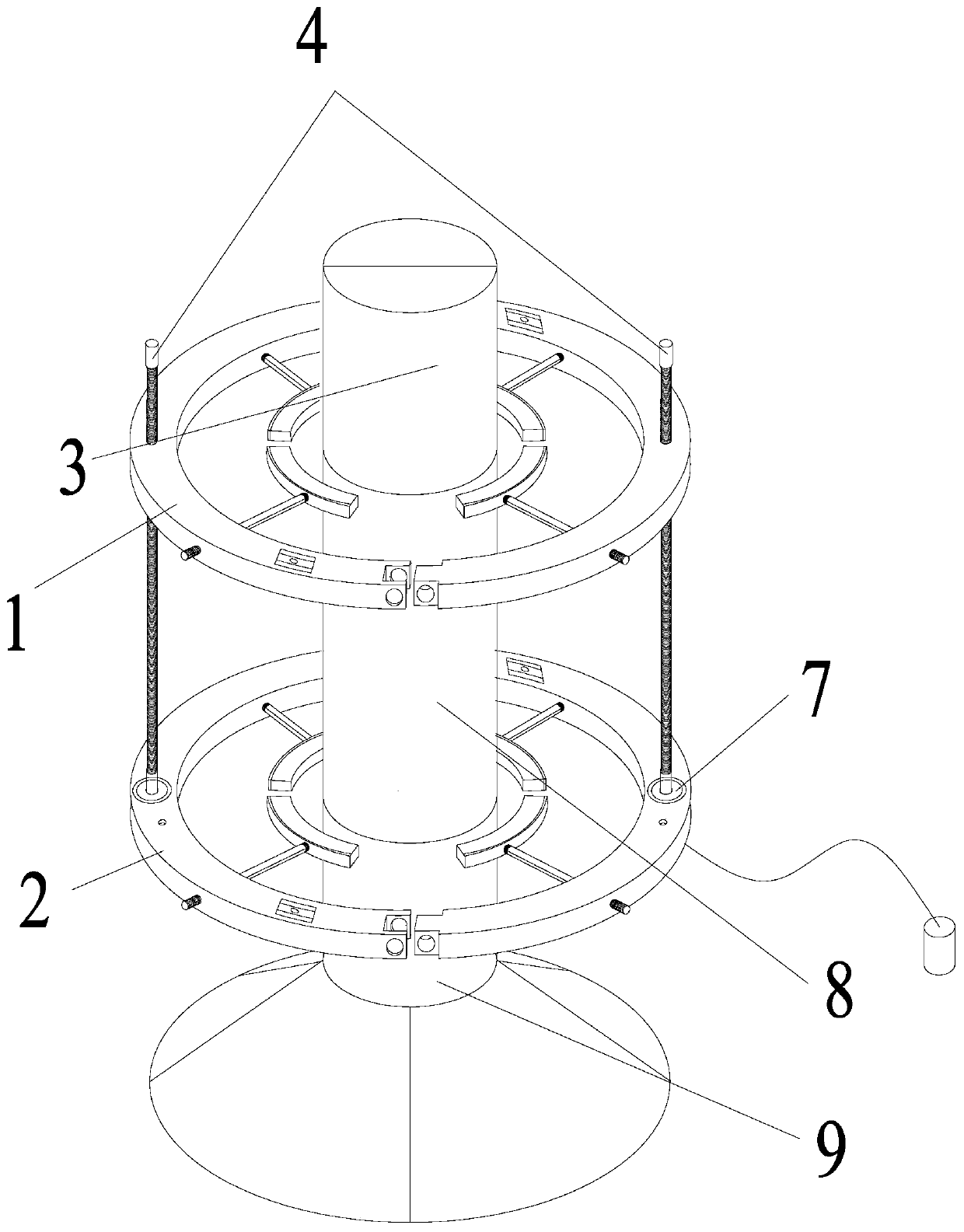
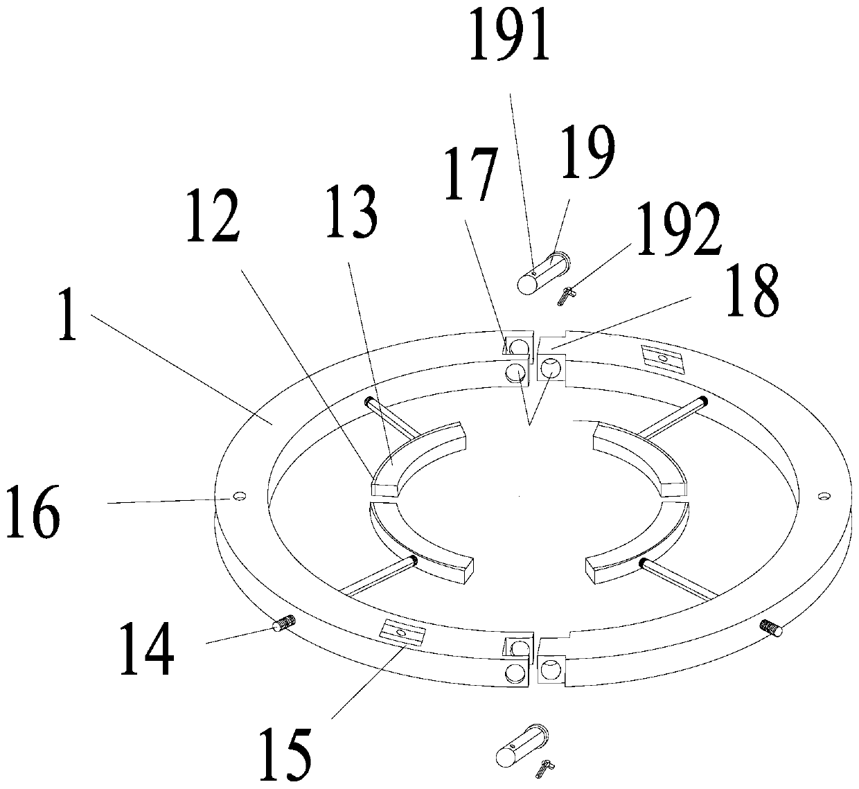
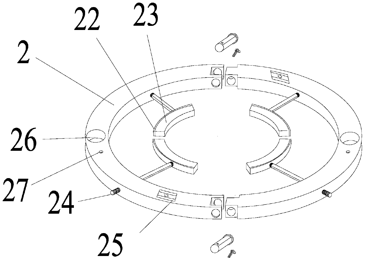
[0024] A rock sample axial extensometer, reference Figures 1 to 5 , comprising an upper ring and a lower ring; the upper ring is formed by splicing two first half rings 1, and the lower ring is formed by splicing two second half rings 2;

[0025] The first semi-circular ring 1 is provided with a first extension rod placement hole 16 and a first columnar horizontal air bubble 15; the side wall of the first semi-circular ring 1 is also provided with two first adjustment holes; The two ends of the first half ring 1 are specifically the first mortise and tenon structural elements; the upper ring also includes a first fixing device; the first fixing device includes four identical and center-symmetrically arranged first arc-shaped stainless steel 12. The outer wall of the first arc-shaped stainless steel 12 is also provided with a first adjustment ...


PUM


Abstract

The invention provides a rock sample axial extensometer. The rock sample axial extensometer comprises an upper circular ring and a lower circular ring; the upper circular ring is formed by splicing two first semicircular rings, and the lower circular ring is formed by splicing two second semicircular rings; the first semicircular rings are provided with first extension rod placement holes and first cylindrical horizontal bubbles; two first adjusting holes are further formed in the side wall of each first semicircular rings; the two tail ends of each first semicircular rings are specifically first mortise-and-tenon structural elements; the upper circular ring further includes a first fixing device; the first fixing device includes four first arc-shaped stainless steel which are identical and are arranged in central symmetry, first adjusting fitting hole are further formed in the outer side walls of the first arc-shaped stainless steel, and first adjusting rods penetrate through the first adjusting holes and the first adjusting fitting holes in sequence to adjust the position of the first arc-shaped stainless steel. By applying the technical scheme, the structure is simple, using isconvenient, and popularization to the field of indoor rock mechanics testing is facilitated.

Description

technical field [0001] The invention relates to the technical field of rock mechanics tests, in particular to a rock sample axial extensometer. Background technique [0002] With the deepening of geotechnical engineering, rock is the most widely distributed natural material in the earth's crust. Mining, water conservancy, tunnels, pipe galleries and other projects often encounter various complex geological conditions. The unique mechanical properties of rock, such as heterogeneity and anisotropy, bring great uncertainty to the construction of rock mass engineering. It is difficult to accurately calculate the mechanical parameters of rock only by relying on theoretical models and numerical simulations. The calculation results are often It tends to be simplistic and is quite different from reality. Therefore, rock mechanics tests have a special status and provide basic data for theoretical derivation and numerical simulation. [0003] Nowadays, with the continuous improvement...

Claims


Application Information

Patent Timeline
Patent Type & Authority Applications(China)
IPC IPC(8): G01N3/02G01N3/06
CPCG01N3/02G01N3/06
Inventor 唐欣俞缙张大山蔡燕燕刘士雨涂兵雄
Owner HUAQIAO UNIVERSITY
Learn More