Supercharge Your Innovation With Domain-Expert AI Agents!

Computer network demultiplexer

A computer network and splitter technology, which is applied in the direction of network connectors, computer peripheral equipment connectors, connections, etc., can solve the problem that the dust-proof and heat-dissipating effect of the network splitter is not ideal, affects the service life of the network splitter, and reduces the network capacity. The practicability of the splitter and other issues can be achieved to achieve a good dust-proof and heat-dissipating effect, improve the heat-dissipating effect, and increase the service life.

Inactive Publication Date: 2020-03-06
户玉珠
View PDF3 Cites 2 Cited by
  • Summary
  • Abstract
  • Description
  • Claims
  • Application Information

AI Technical Summary

Problems solved by technology

[0002] The application of computers is becoming more and more common in China. After the reform and opening up, the number of computer users in China has continued to rise, and the application level has continued to improve. In particular, the applications in the fields of Internet, communication, and multimedia have achieved good results. It is inconvenient to detect when the splitter fails, which leads to inconvenience in use, waste of time, inconvenient operation, and cannot be known in time when there is no signal, and the traditional splitter is a simple connector. It is inconvenient to install and fix. In the existing network communication splitter, when connecting multiple network lines, due to the force generated between the multiple network lines, the network line is easy to detach from the splitter, resulting in The middle end of the communication is reduced, and the practicability of the network splitter is reduced. At the same time, the dust-proof and heat-dissipating effect of the existing network splitter is not ideal, which affects the service life of the network splitter

Method used


Image

  • Computer network demultiplexer
  • Computer network demultiplexer
  • Computer network demultiplexer

Examples


Embodiment Construction

[0023] The present invention will be further described below in conjunction with specific embodiments, wherein, the accompanying drawings are only for exemplary illustrations, and what is shown is only a schematic diagram, rather than a physical map, and cannot be understood as a limitation to this patent. In order to better illustrate the present invention Specific embodiments, some parts in the drawings will be omitted, enlarged or reduced, and do not represent the size of the actual product. For those skilled in the art, it is understandable that some known structures and their descriptions in the drawings may be omitted. Based on The specific implementation modes in the present invention and all other specific implementation modes obtained by persons of ordinary skill in the art without making creative efforts all belong to the protection scope of the present invention.

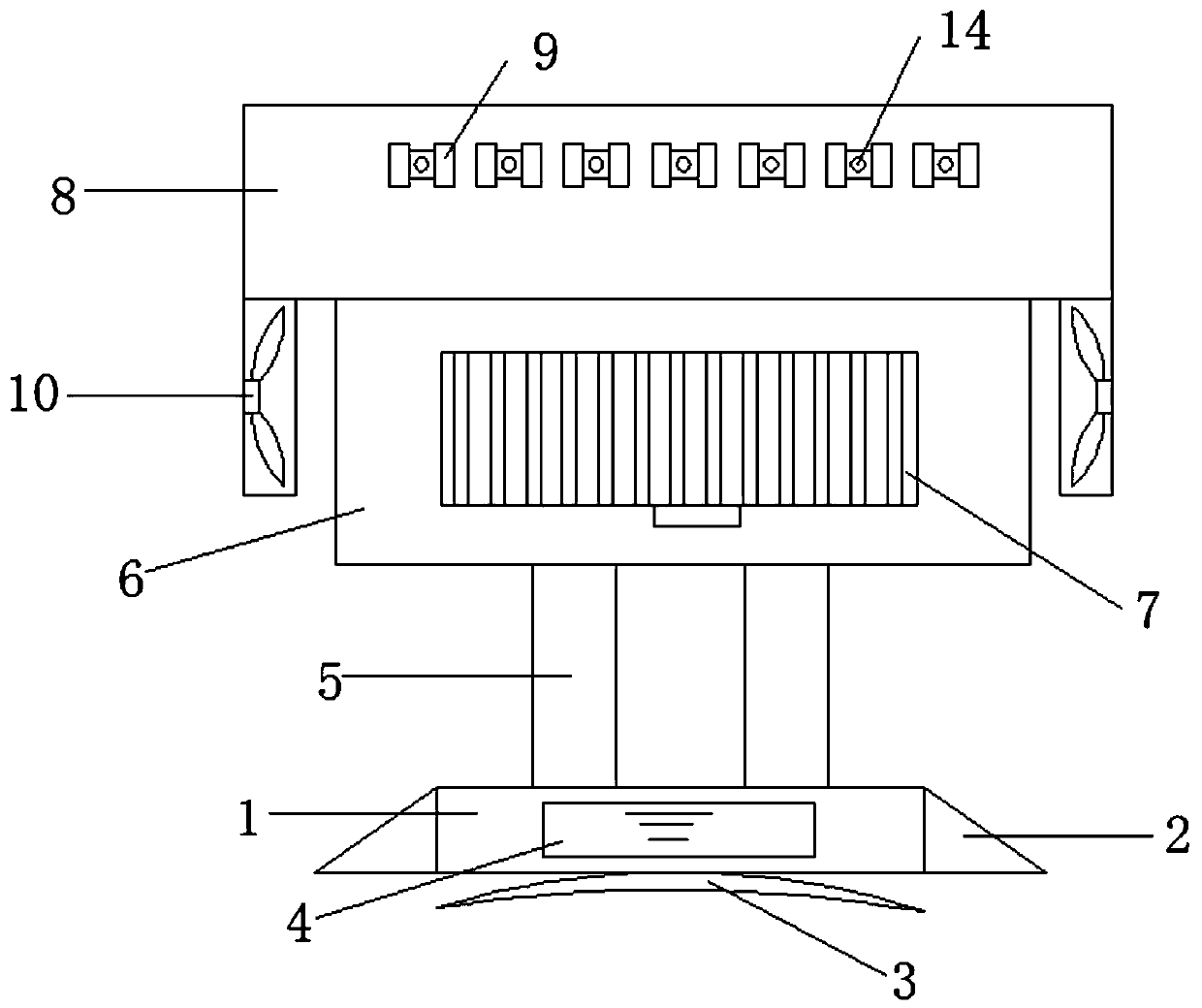
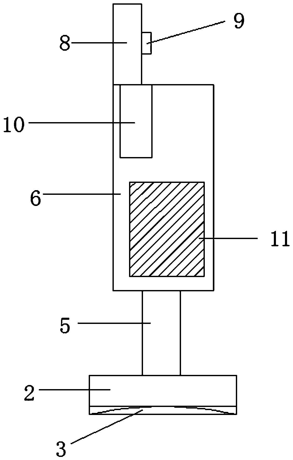
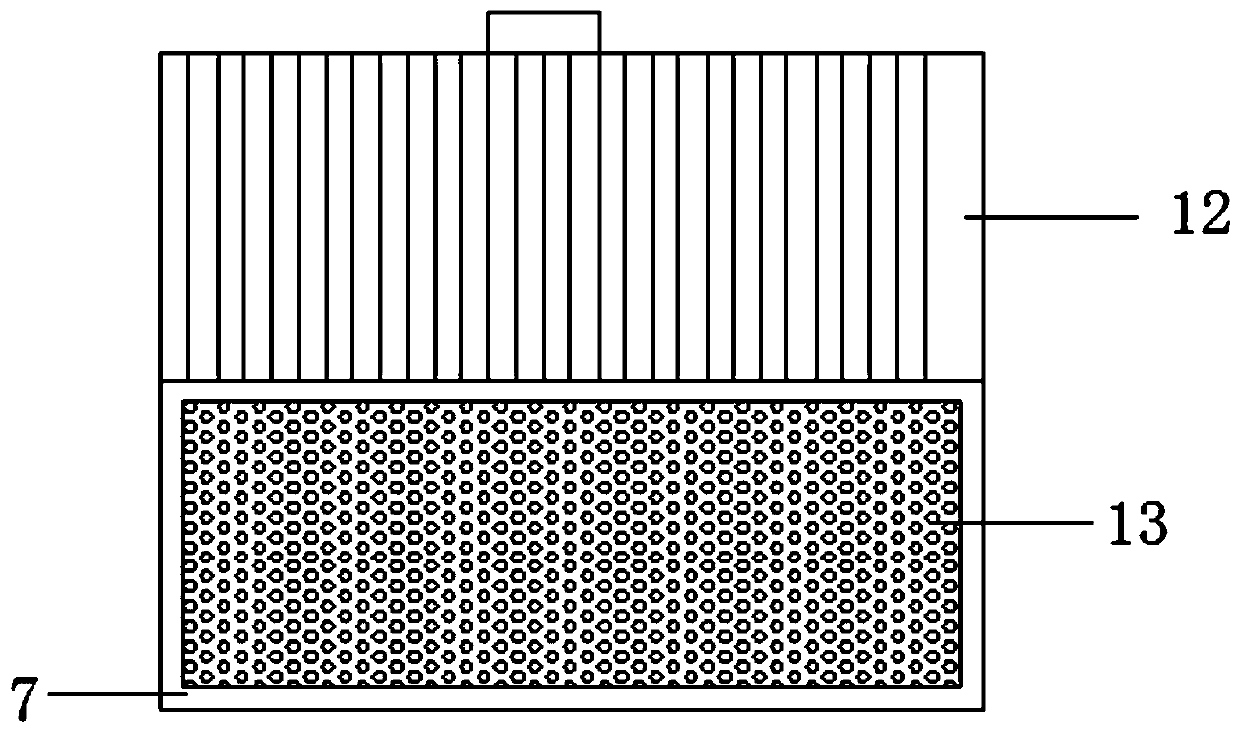
[0024] Such as Figure 1-6 As shown, a computer network splitter includes a base 1, the left and right...


PUM


Abstract

The invention relates to a computer network demultiplexer, which comprises a base. Reinforcing plates are arranged on the left side and the right side of the base, a suction cup is fixedly connected to the bottom of the base, a battery box is arranged on the base, a buffer device is fixedly connected to the top of the base, a network demultiplexer body is fixedly connected to the top of the bufferdevice, a dust collection box is arranged on the network demultiplexer body, the dust collection box is composed of a box cover and a box body, the box cover is movably connected with the box body through a hinge, a dust filter screen is further arranged in the box body, a wire distribution plate is fixedly connected to the top of the network demultiplexer body, a wire pressing plate is fixedly connected to the wire distribution plate, a first threaded hole is formed in the top of the wire pressing plate, and a first adjusting screw rod is in threaded connection with the first threaded hole.The overall structure has good dustproof and heat dissipation effects and good buffer protection capacity, fixing of a network cable connector and separation of a network cable are effectively achieved, use is convenient, and the service life is prolonged.

Description

technical field [0001] The invention relates to a computer network splitter, which belongs to the field of network equipment. Background technique [0002] The application of computers is becoming more and more common in China. After the reform and opening up, the number of computer users in China has continued to rise, and the application level has continued to improve. In particular, the applications in the fields of Internet, communication, and multimedia have achieved good results. It is inconvenient to detect when the splitter fails, which leads to inconvenience in use, waste of time, inconvenient operation, and cannot be known in time when there is no signal, and the traditional splitter is a simple connector. It is inconvenient to install and fix. In the existing network communication splitter, when connecting multiple network lines, due to the force generated between the multiple network lines, the network line is easy to detach from the splitter, resulting in The m...

Claims


Application Information

Patent Timeline
Patent Type & Authority Applications(China)
IPC IPC(8): H01R13/621H01R13/72H01R13/73H01R13/52H01R13/502H01R13/66H01R13/717H05K7/20B01D46/10
CPCB01D46/10H01R13/502H01R13/52H01R13/6215H01R13/6675H01R13/717H01R13/72H01R13/73H01R2201/04H01R2201/06H05K7/20136
Inventor 户玉珠
Owner 户玉珠
Features
  • R&D
  • Intellectual Property
  • Life Sciences
  • Materials
  • Tech Scout
  • Unparalleled Data Quality
  • Higher Quality Content
  • 60% Fewer Hallucinations
Learn More