

Motor heat dissipation device of electric locomotive
A technology of heat dissipation device and motor heat dissipation, applied in the direction of electromechanical device, cooling/ventilation device, electrical components, etc., can solve the problem of not being able to work for a long time, increase explosion-proof measures, etc., to extend the working time, prolong the working time, and increase the application. the effect of the occasion
- Summary
- Abstract
- Description
- Claims
- Application Information
AI Technical Summary
Problems solved by technology
Method used
Image

Examples
Embodiment 1
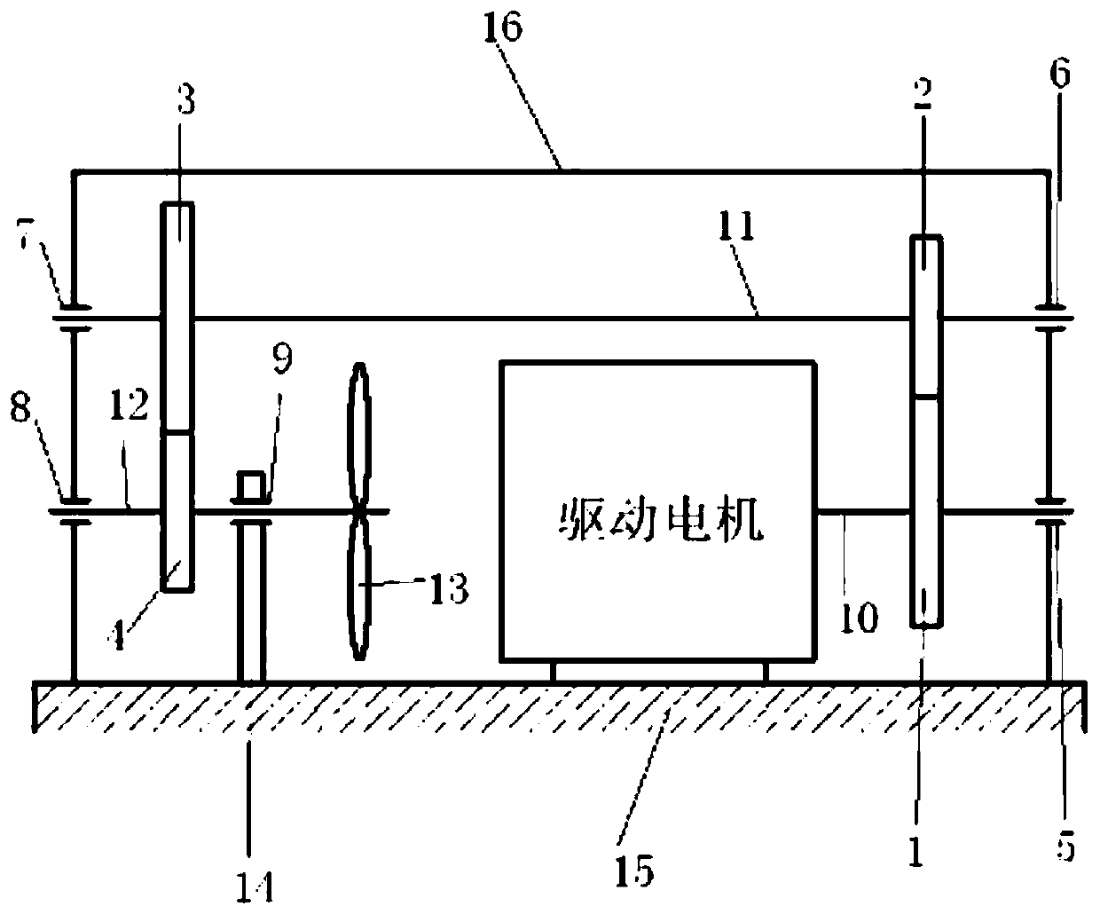
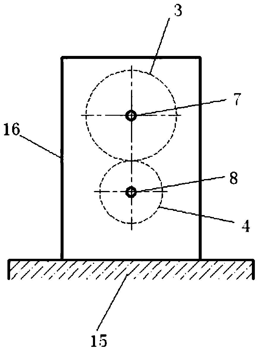
[0023] Such as figure 1 Shown: the electric locomotive motor cooling device, including the cooling device housing 16, gears, transmission shafts, rolling bearings, fan blades, frame, the driving motor is installed in the cooling device housing 16, and the driving motor output spindle 10 is installed respectively from left to right The driving motor, the first gear 1, the first rolling bearing 5, the third rolling bearing 7, the third gear 3, the second gear 2, the second rolling bearing 6 are respectively connected to the first transmission shaft 11 from left to right, and the second transmission The fourth rolling bearing 8, the fourth gear 4, the fifth rolling bearing 9, and the fan blade 13 are respectively installed on the shaft 12 from left to right. The first gear 1 meshes with the second gear 2 , and the third gear 3 meshes with the fourth gear 4 .
[0024] Both the drive motor and the heat sink housing 16 are fixed on the frame 15 . The first gear 1 , the second gear...
PUM
 Abstract
Description
Claims
Application Information