
Extractor hood convenient to clean

A range hood and cleaning technology, applied in the removal of oil fume, heating method, household heating and other directions, can solve the problems of inability to quickly disassemble by itself, obstacles to users' daily cleaning, and many dead spots in cleaning, to protect the electronic control part and wiring, The effect of simplified structure and convenient cleaning

Inactive Publication Date: 2020-03-10
HUNAN XUNDA JI TUAN YOU XIAN GONG SI
View PDF0 Cites 0 Cited by
  • Summary
  • Abstract
  • Description
  • Claims
  • Application Information

AI Technical Summary

Problems solved by technology

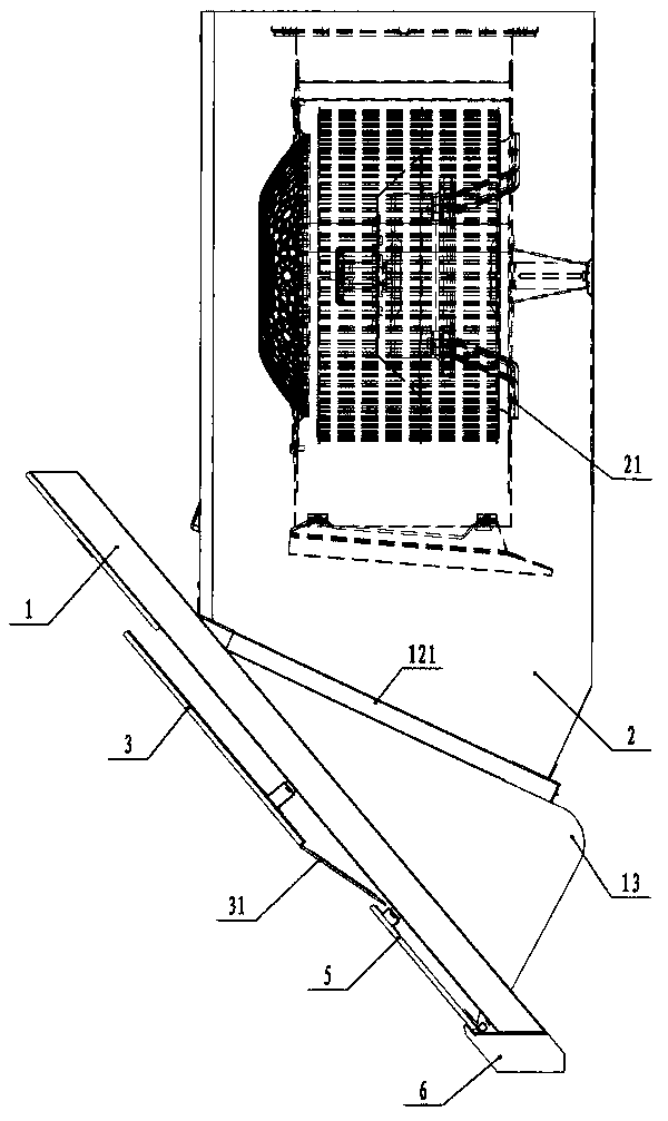
[0003] At present, most of the existing range hoods adopt the structure of "condensing plate + panel (smoke collecting hood) + filter screen + smoke collecting cavity + chassis", and the smoke collecting cavity and panel are spliced ​​by multiple sheet metals, and the structure is complex. There are many dead corners for cleaning, and it is easy to deposit oil. At the same time, the condensing plates are also fixed installations and cannot be quickly disassembled by themselves, which has caused considerable obstacles to the daily cleaning of users.

Method used


Image

  • Extractor hood convenient to clean
  • Extractor hood convenient to clean
  • Extractor hood convenient to clean

Examples


Embodiment 1

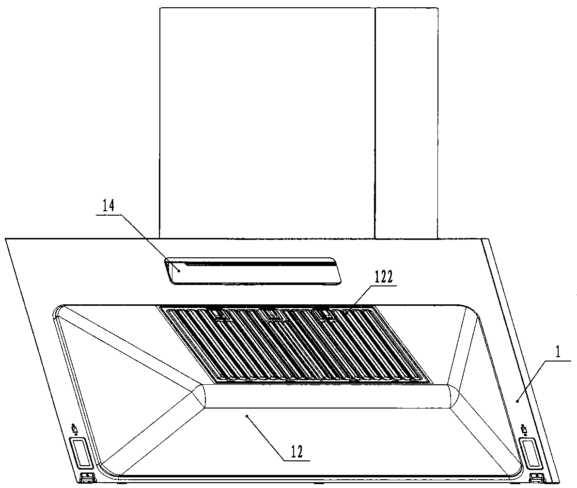
[0017] refer to Figure 1 to Figure 2 , a convenient and clean range hood, comprising a panel 1 and a chassis 2, the surface of the panel 1 is equipped with a condensing plate 3, and in a normal installation state, the panel 1 and the horizontal plane form a certain angle of inclination, the chassis 2 A fan system 21 is installed, and the panel 1 is provided with a smoke collection cavity 12 integrally formed with the panel 1. The smoke collection cavity 12 is a concave structure, and an air inlet 121 is opened on the upper stretching surface, and the smoke collection cavity 12 passes through The air inlet 121 is directly connected with the chassis 2 . The oil tank 6 is placed below the panel 1, and the oil dirt filtered and condensed by the blower fan, the filter screen and the smoke collection chamber flows into the oil tank 6 through the smoke collection chamber.

[0018] The filter screen 122 that is easy to disassemble is installed on the air inlet 121, and the user can ...

Embodiment 2

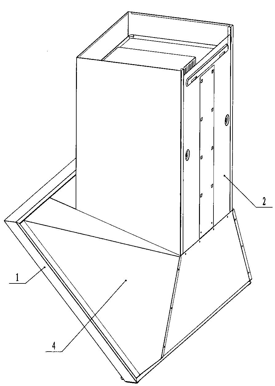
[0024] refer to image 3 The difference between this embodiment and the first embodiment is that: the back side 13 of the panel 1 is also equipped with a decorative cover 4, the part protruding from the smoke collection chamber 12 and the rivets or screws that may exist at the connection with the chassis 2 The exposed connecting parts cover it, which improves the appearance of the whole range hood to a higher level. At the same time, the space between the panel and the cover plate 4 is completely sealed, and there is no soot gas to enter, so the electric control wires arranged in the middle can be protected from corrosion, the usual electric control wires are arranged in the air duct of the chassis, and the original The electronic control part usually installed on the top of the range hood is directly installed in it, which simplifies wiring and better forms protection.

Embodiment 3

[0026] refer to Figure 4 The difference between this embodiment and the first and second embodiments is that the condensation plate 3 can also be a flap-type opening and closing structure.


PUM


Abstract

The invention discloses an extractor hood convenient to clean. The extractor hood convenient to clean comprises a panel and a machine case. A condensation plate is mounted on the surface of the panel.In a normal installation state, an included angle is formed between the panel and the horizontal plane. A draught fan system is mounted in the machine case. The panel is provided with a fume collection cavity integrally formed with the panel. The fume collection cavity is directly connected with the machine case. The position where the fume collection cavity is connected with the machine case isprovided with an air inlet. Compared with the prior art, the extractor hood convenient to clean has the beneficial effects that the extractor hood convenient to clean is simple in structure and free of cleaning dead angles; and after the condensation plate is quickly dismantled, the whole fume collection cavity is a composite curved surface, and a user can clean the fume collection cavity conveniently.

Description

technical field [0001] The invention relates to a convenient and clean range hood. Background technique [0002] As a common electrical appliance in our daily life, the range hood is widely used. It is a kitchen appliance that purifies the kitchen environment. Suck it away, discharge it outside, and play the role of purifying the air. [0003] At present, most of the existing range hoods adopt the structure of "condensing plate + panel (smoke collecting hood) + filter screen + smoke collecting cavity + chassis", and the smoke collecting cavity and panel are spliced ​​by multiple sheet metals, and the structure is complex. There are many dead corners for cleaning, and it is easy to deposit oil. At the same time, the condensing plates are also fixed installations and cannot be quickly disassembled by themselves, which has caused considerable obstacles to the daily cleaning of users. Contents of the invention [0004] The technical problem to be solved by the present invent...

Claims


Application Information

Patent Timeline
Patent Type & Authority Applications(China)
IPC IPC(8): F24C15/20
CPCF24C15/2035
Inventor 刘朝辉陈高洁伍奕
Owner HUNAN XUNDA JI TUAN YOU XIAN GONG SI
Learn More