Multifunctional cooking utensil

A cooking utensil and multi-functional technology, which is applied in the field of multi-functional cooking utensils, can solve problems such as damage to motors or components, and affect the service life of multi-functional cooking utensils, and achieve the effects of improving thermal efficiency, ensuring safety in use, and improving service life

Inactive Publication Date: 2020-03-13
JOYOUNG CO LTD
View PDF7 Cites 14 Cited by
  • Summary
  • Abstract
  • Description
  • Claims
  • Application Information

AI Technical Summary

Problems solved by technology

However, during the working process of this multifunctional cooking appliance, steam will enter the motor or components. Since moisture is often entrained in the steam, the steam will damage the motor or components, and affect the service life of the multifunctional cooking appliance.

Method used


Image

  • Multifunctional cooking utensil
  • Multifunctional cooking utensil
  • Multifunctional cooking utensil

Examples


Embodiment 1

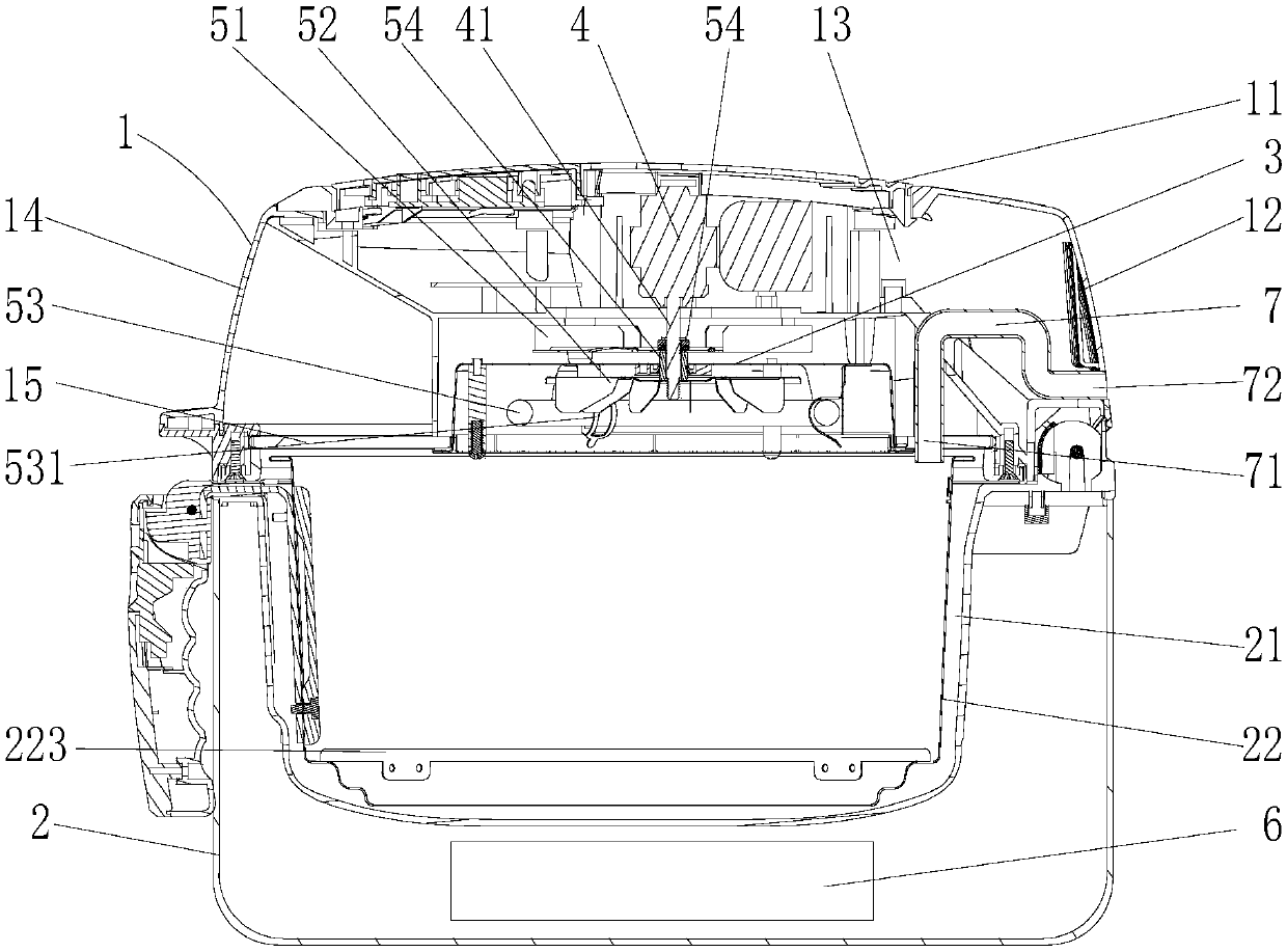
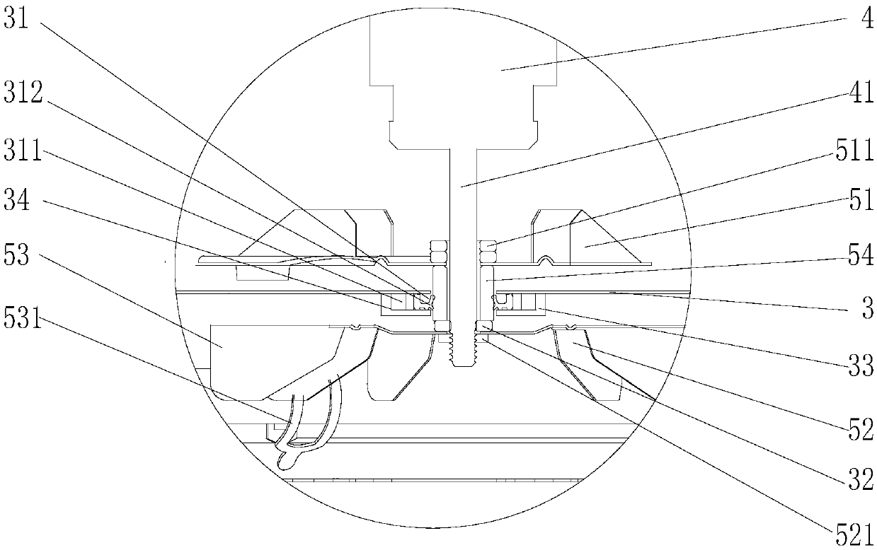
[0039] The structure of the multifunctional cooking appliance of the present embodiment is as follows: Figure 1 to Figure 2 As shown, the multifunctional cooking appliance includes an upper casing 1 and a lower casing 2, both of which are heat-resistant plastic casings, and the upper casing 1 is covered on the lower casing 2. In this embodiment The upper casing 1 and the lower casing 2 of the example are hinged to each other, the upper casing 1 is arranged above the lower casing 2 through a hinge shaft, and the upper casing 1 is provided with an air inlet 11 and an air outlet 12, and the air inlet 11 is located on the upper casing. The top of the body 1 has a short air intake path, so that the outside air quickly enters the cold air cavity 13 to dissipate heat for the motor, improving heat dissipation efficiency. The air outlet 12 is located on the rear side of the upper housing 1 to reduce the impact of the air on the user. A wind guide cover 3 is arranged under the upper sh...

Embodiment 2

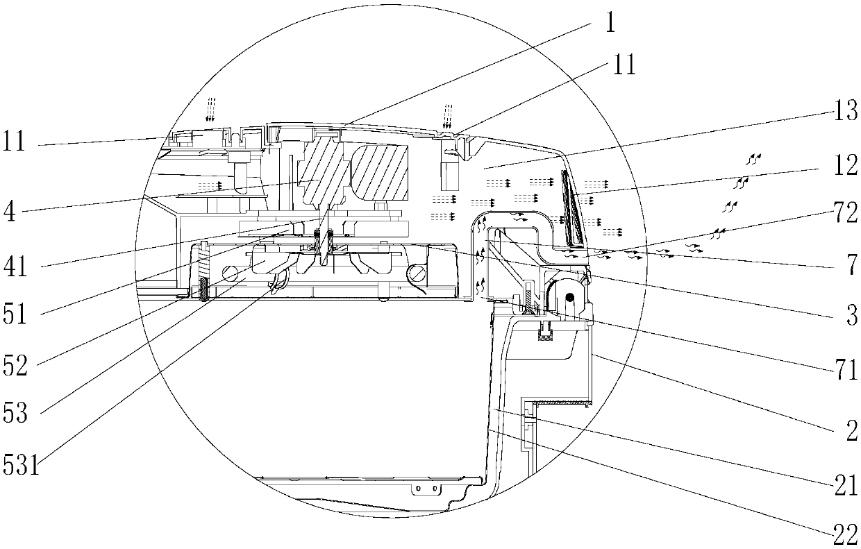
[0051] The difference between this embodiment and Embodiment 1 lies in the specific structure of the steam exhaust channel, combined with image 3As shown, the second communication port 72 of the steam exhaust passage 7 of this embodiment is located on the upper casing 1 and is located on a different side from the air inlet 11, specifically, the air inlet 11 is located on the top of the upper casing 1, that is, on the top of the cover 14 To communicate with the cold air chamber 13, the second communication port 72 is located at the side of the upper case 1, that is, at the side of the cover body 14 to communicate with the outside world, so that the second communication port 72 and the air inlet 11 are on different sides of the upper case 1 Set to reduce the probability that the steam discharged from the second communication port 72 will enter the cold air chamber 13 through the air inlet 11 and damage the motor 4 and components, and the air inlet 11 is located on the top of the...

Embodiment 3

[0061] The difference between this embodiment and Embodiment 1 or Embodiment 2 is that a condensed water box 16 is provided on the side of the upper casing 1, combined with Figure 4 As shown, the condensed water box 16 of this embodiment is detachably installed, and the condensed water box 16 is set on the same side as the second communicating port 72 and is located below the second communicating port 72, most of the steam will pass through the second communicating port 72 However, a small amount of steam will still form condensed water when it is cooled. At this time, the condensed water generated by the steam will be collected downwards at the second communication port 72 and enter the condensed water box 16 to prevent the condensed water from The outer walls of the upper casing 1 and the lower casing 2 drip onto the table, which improves the experience of the user.

[0062] Other structures and beneficial effects of this embodiment are the same as those of Embodiment 1 or ...


PUM


Abstract

The invention discloses a multifunctional cooking utensil. The multifunctional cooking utensil comprises an upper shell and a lower shell, an air inlet and an air outlet are formed in the upper shell;a air guide cover r is arranged below the upper shell; a cold air cavity is defined between the upper shell and the air guide cover; the air inlet and the air outlet are communicated with the cold air cavity; a motor and a cold air fan are arranged in the cold air cavity; the cold air fan is fixedly connected with a motor shaft of the motor; a hot air fan and a heating element are arranged belowthe air guide cover; a motor shaft penetrates through the air guide cover and then is fixedly connected with the hot air fan; a containing cavity is formed in the lower shell body, a container is arranged in the containing cavity, the multifunctional cooking utensil further comprises a steam generation device for providing steam for the container. The cold air cavity is hermetically separated fromthe containing cavity; and a steam exhaust channel is formed in the upper shell, a first communicating opening of the steam exhaust channel communicates with the containing cavity, a second communicating opening of the steam exhaust channel communicates with the outside, and the second communicating opening is located in the upper shell and is formed in the side different from the side provided with the air inlet.

Description

technical field [0001] The invention belongs to the field of kitchen appliances, in particular to a multifunctional cooking appliance. Background technique [0002] Traditional cooking utensils have relatively single functions, and usually only have a certain function of cooking utensils, such as steaming or roasting or boiling. In order to meet the needs of users, multi-functional cooking appliances have emerged as the times require. Existing multi-functional cooking appliances often have two or more functions of cooking appliances, for example, both steaming and roasting functions, or both roasting and boiling functions. , which satisfies the needs of users to a certain extent. However, during the working process of this multifunctional cooking appliance, steam will enter the motor or components. Since moisture is often entrained in the steam, the steam will damage the motor or components, and affect the service life of the multifunctional cooking appliance. . Contents...

Claims


Application Information

Patent Timeline
Patent Type & Authority Applications(China)
IPC IPC(8): A47J27/04A47J37/06A47J36/38
CPCA47J27/04A47J36/38A47J37/0641A47J2027/043
Inventor 王旭宁张铮金恩来张雪岩
Owner JOYOUNG CO LTD
Why Eureka
Try Eureka