Height-adjustable casting mold machining clamping mechanism

A technology for casting molds and clamping mechanisms, which is applied in the direction of manufacturing tools, metal processing equipment, grinding workpiece supports, etc., can solve problems such as unfavorable promotion and use, increase resource consumption, and increase use costs, so as to save resources and save Resource, resource saving effect

Active Publication Date: 2020-03-13
HANSHAN COUNTY XINGDA DUCTILE IRON FACTORY
View PDF5 Cites 4 Cited by
  • Summary
  • Abstract
  • Description
  • Claims
  • Application Information

AI Technical Summary

Problems solved by technology

When the mechanism moves the left and right sides of the mold, it clamps by moving the support plates on the left and right sides, which greatly improves the consumption of resources, and the cost of use is high. When adjusting the height of the mold, it also uses two sets of motors to adjust the height of the mold. drive, which also increases the cost of use, which is not conducive to the promotion of use

Method used


Image

  • Height-adjustable casting mold machining clamping mechanism
  • Height-adjustable casting mold machining clamping mechanism
  • Height-adjustable casting mold machining clamping mechanism

Examples


Embodiment 1

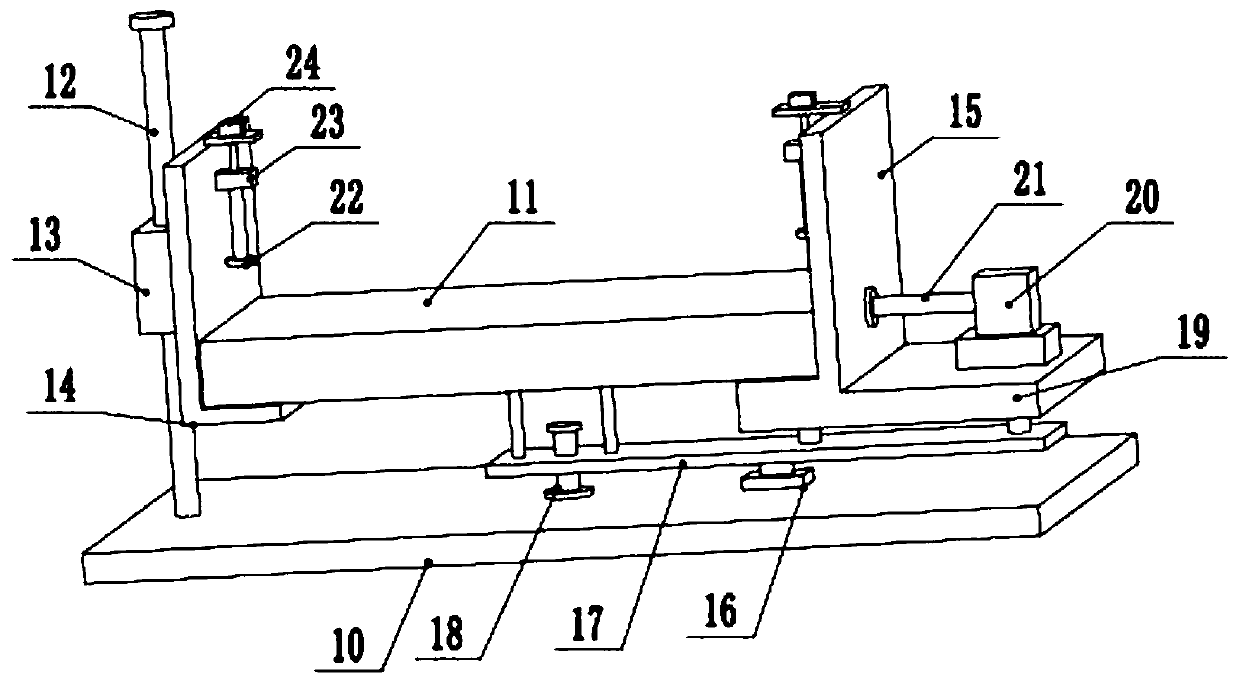
[0021] see Figure 1-2 , a height-adjustable clamping mechanism for casting mold processing, including a base plate 10, a fixed support plate 14, and a movable support plate 15; There is a sliding sleeve 13, the top of the sliding rod 12 is fixedly installed with a limit plate to prevent the sliding sleeve 13 from falling off, and the right side of the sliding sleeve 13 is fixedly installed with a fixed supporting plate 14 in an L-shaped structure, which is located on the right side of the fixed supporting plate 14 A group of movable pallets 15 symmetrical to the fixed pallet 14 are arranged above the bottom plate 10, and the casting mold 11 to be clamped is placed between the two through the supporting effect of the fixed pallet 14 and the movable pallet 15. . The inner and outer surfaces of the fixed pallet 14 and the movable pallet 15 are all laid with a rubber pad for preventing abrasion of the outer surface of the casting mold 11 . The tops of the fixed supporting plate...

Embodiment 2

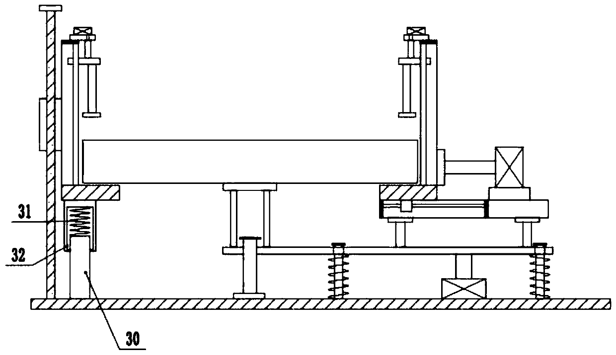
[0026] refer to image 3 , on the basis of Embodiment 1, a group of buffer frames 31 with lower side openings are fixedly installed on the lower surface of the bottom of the fixed pallet 14, and a group of pillars 30 with bottoms fixed on the upper surface of the bottom plate 10 are arranged inside the buffer frame 31, and the pillars The top of 30 is elastically connected by spring 28 before the inner top of buffer frame 31. By setting pillar 30 and buffer frame 31 at the bottom of fixed pallet 14, it is used to slow down fixed pallet 14 when it is stationary or moves up and down. The fixed pallet 14 and the casting mold 11 on the upper side of the fixed pallet 14 exert downward gravity on the right movable pallet 15, thereby further improving the force balance between the left and right groups.


PUM


Abstract

The invention relates to the technical field of casting equipment and discloses a height-adjustable casting mold machining clamping mechanism comprising a bottom plate, fixed support plates and movable support plates. The set of movable support plates symmetrical with the fixed support plates are arranged in the position, on the right sides of the fixed support plates, above the bottom plate. Thetops of the fixed support plates and the movable support plates are each fixedly provided with a set of lifts. Lifting rods are connected to the lower side output ends of the lifts. Horizontal slidingplates are fixedly installed on the bottom inner sides of the lifting rods. Pressing plates are downwards installed at the bottoms of the sliding plates. Transverse piston rods are rightwards fixedlyinstalled on the lower portions of the right side faces of the movable support plates. Cylinders are arranged at the right ends of the piston rods. A transverse supporting plate is fixedly installedin the position, at the bottoms of two sets of struts, on the lower side of a fixed seat. The middle of the lower surface of the bottom of the supporting plate is downwards connected with a hydraulicrod. A strut fixed to the upper surface of the bottom plate is arranged at the bottom of the hydraulic rod. The height-adjustable casting mold machining clamping mechanism has the advantages that operation is easy, clamping force is high, stability is good, resources are saved, and use cost is low.

Description

technical field [0001] The invention relates to the technical field of casting equipment, in particular to a height-adjustable casting mold processing clamping mechanism. Background technique [0002] After the existing casting mold is finished casting, the internal surface needs to be cleaned, and it needs to be fixed manually, and then it needs to be polished, and it needs to be fixed before the grinding treatment. [0003] Chinese patent (notification number: CN 109333354 A, announcement date: 2019.02.15) discloses a height-adjustable clamping mechanism for casting mold processing, including a lifting frame and a bottom mounting frame, and the left and right sides of the top plate of the bottom mounting frame are A vertical side support plate is fixed on the top surface, an upper horizontal plate is fixed on the upper part of the two vertical side support plates close to the wall, two vertical screws are respectively close to the corresponding vertical side support plates...

Claims


Application Information

Patent Timeline
Patent Type & Authority Applications(China)
IPC IPC(8): B24B19/20B24B41/06B24B41/00B24B47/06
CPCB24B19/20B24B41/007B24B41/06B24B47/06
Inventor 张福新
Owner HANSHAN COUNTY XINGDA DUCTILE IRON FACTORY
Why Eureka
Try Eureka