Cuff sewing machine

A machine and body technology, applied in the direction of cloth feeding mechanism, sewing machine components, sewing machine control devices, etc., can solve the problems of low efficiency, different cuff tightness, inconsistent worker proficiency, etc., and achieve high efficiency.

Pending Publication Date: 2020-03-13
STRONG H MACHINERY TECH
View PDF0 Cites 1 Cited by
  • Summary
  • Abstract
  • Description
  • Claims
  • Application Information

AI Technical Summary

Problems solved by technology

[0002] At present, the garment processing industry sews the threaded cuffs to the sleeves manually. When sewing, the circular threaded cuffs are manually stretched to the matching width of the cuffs and then manually sewed in circles. The common problem is due to the proficiency of workers. Inconsistent, resulting in varying degrees of tightness of the cuff across the range of travel, and very inefficient

Method used


Image

  • Cuff sewing machine
  • Cuff sewing machine
  • Cuff sewing machine

Examples


Embodiment 1

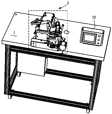
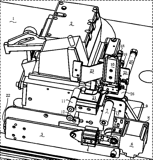
[0021] Example 1, such as Figure 1-4 The upper cuff machine shown includes a machine platform 1, on which an overlock sewing machine 2 is fixed, and the overlock sewing machine 1 has a needle board platform 21, and the first A mounting plate 3, the middle part of the first mounting plate 3 is hinged with the cylinder body of the first cylinder 4, and the end is hinged to the lower end of the support plate 5, and the support plate 5 is located on the right side of the needle plate platform 21. The cylinder rod of the first air cylinder 4 is hinged with the middle part of the support plate 5, and the top of the support plate 5 is fixedly connected with the drive motor mounting plate 8 and the drive roller mounting plate 71, and the drive motor is fixed on the drive motor mounting plate 8. 6. The driving motor shaft of the driving motor 6 is fixed with a driving synchronous pulley, and the driving roller mounting plate 71 is pivotally provided with a cloth supporting driving rol...

Embodiment 2

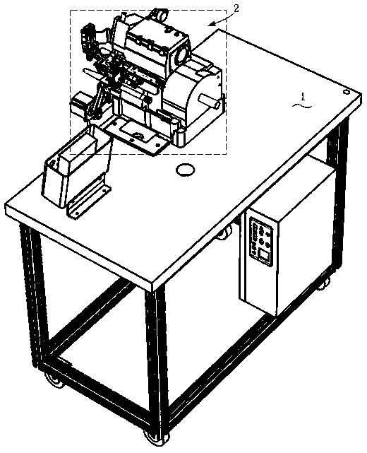
[0031] Example 2, such as Figure 5-6 Another upper cuff machine shown is different from Embodiment 1 in that the turning support mechanism includes a first mounting plate 3 arranged on the body of the overlock sewing machine 2, and the middle part of the first mounting plate 3 is hinged. The cylinder body of the first cylinder 4, the lower end of the end hinged support plate 5 are established, and the support plate 5 is positioned at the right side of the needle plate platform 21, and the cylinder rod of the first cylinder 4 is connected to the support plate 5. The middle part is hinged, and the upper part of the support plate 5 is fixedly connected to the first guide rail 51 arranged front and back, and the front end of the first guide rail 51 is fixed with an adjustment motor 53, which is slidingly matched with the first slider 52, and the motor shaft of the adjustment motor 53 is fixed. Connect the screw rod 54 whose axial direction is the front and rear direction. The fir...


PUM


Abstract

The invention discloses a cuff sewing machine, which comprises a table; a flat seaming machine is fixedly arranged on the table, the flat seaming machine is provided with a needle plate platform; unlike the prior art, the cuff sewing machine also comprises a rotary supporting mechanism; the rotary supporting mechanism can support or loosen sleeves and cuffs stacked together and enable the sleevesand the cuffs to rotate in a reciprocating mode and to slide on the upper surface of the needle plate table of the flat seaming machine. Compared with the prior art, the cuff sewing machine has the advantages that manual sewing of cuffs can be replaced, the efficiency is high, and the cuff sewing machine has the capacity the same as that of about tens workers.

Description

technical field [0001] The invention relates to clothing equipment, in particular to a cuff-fitting machine. Background technique [0002] At present, the garment processing industry sews the threaded cuffs to the sleeves manually. When sewing, the circular threaded cuffs are manually stretched to the matching width of the cuffs and then manually sewed in circles. The common problem is due to the proficiency of workers. Inconsistency, resulting in varying degrees of tightness of the cuffs in the range of travel, and very inefficient. Contents of the invention [0003] The purpose of the present invention is to overcome the deficiencies in the prior art, disclose this kind of cuff machine that can automatically tighten the threaded cuff and the sleeve opening to the same degree in the circumferential range and automatically rotate and sew, the technical solution adopted is : [0004] This kind of upper cuff machine includes a machine platform on which an overlock sewing m...

Claims


Application Information

Patent Timeline
Patent Type & Authority Applications(China)
IPC IPC(8): D05B21/00D05B35/02D05B69/00
CPCD05B21/007D05B35/02D05B69/00D05D2305/34
Inventor 李志朝
Owner STRONG H MACHINERY TECH
Why Eureka
Try Eureka