Skewer stringing machine
A threading and stringing technology is applied in the field of devices for threading ingredients into strings in the catering industry, which can solve the problems of complex machine structure, high labor cost, complicated work and other problems, and achieve the effects of cost reduction, simple operation and simple structure.
- Summary
- Abstract
- Description
- Claims
- Application Information
AI Technical Summary
Problems solved by technology
Method used
Image
Examples
Embodiment 1
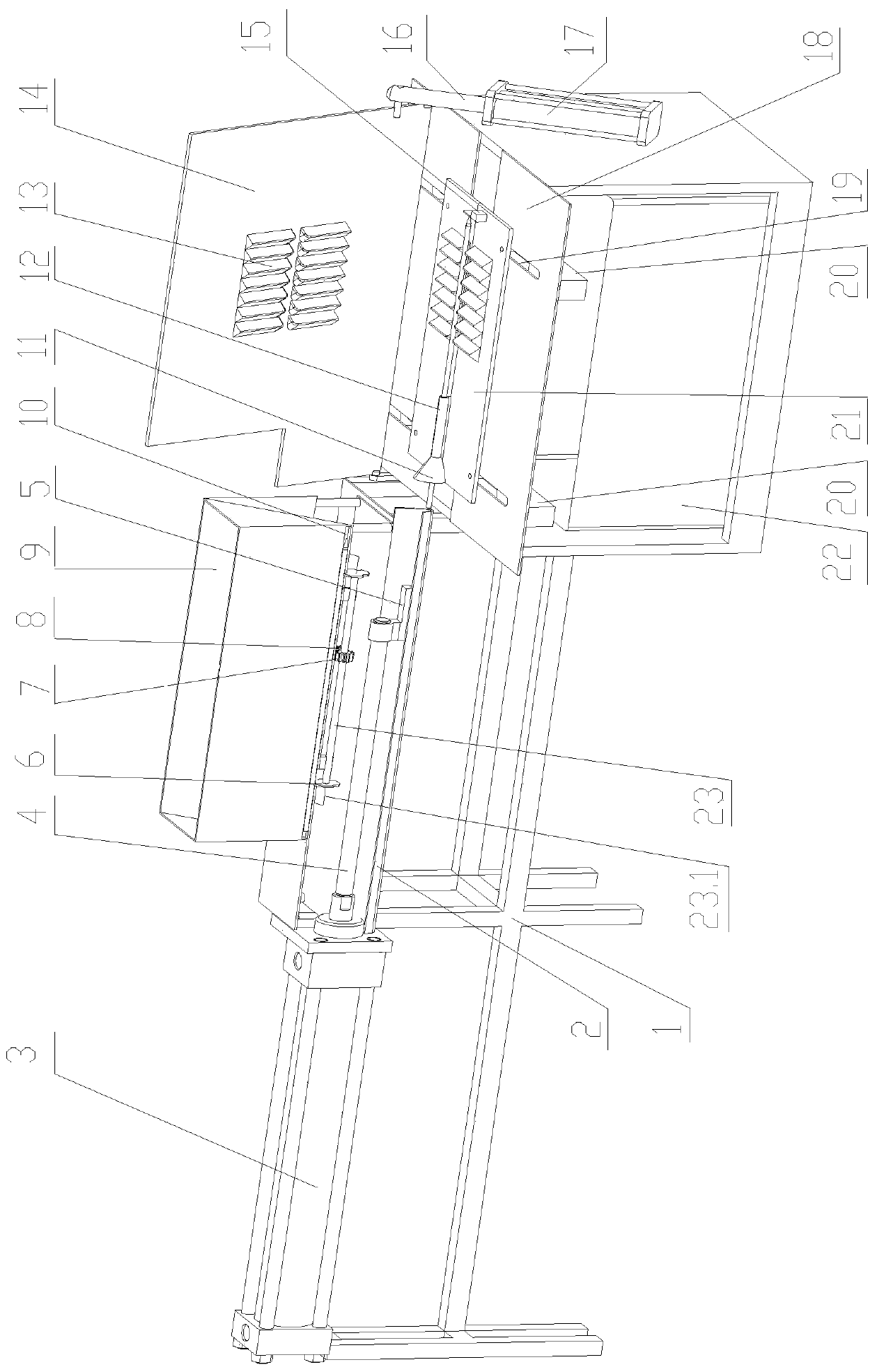
[0022] see figure 1 , Figure 4 ~ Figure 7 , Figure 9 , Figure 10 , the present invention includes a food material fixing device, a skewer putting device, a skewer pushing device and a skewer collection box 22. The lower splint 21, the side of the lower splint 21 is hinged to the upper splint 14; the upper splint 14 is provided with two rows of food tanks 13 on the left and right, and there is a gap 14.1 between the two food tanks 13 for the string 27 to pass through, and the lower splint 21 is separated from the left and right Type splint, on the left splint and the right splint, respectively be provided with food material groove 13, on the opposite side wall of one end of the left splint and the right splint, respectively set two sections of cavities with a semi-arc cross section, so that when the left splint and the right splint are closed, two The section cavities form the connected tapered hole 11 and the string sign guide tube 12 respectively. When the left splint a...
Embodiment 2
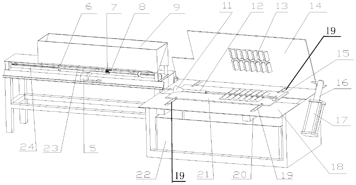
[0032] see figure 2 , Figure 4 ~ Figure 6 , Figure 8 ~ Figure 10 , the other structure of this embodiment is the same as that of Embodiment 1, the difference is as follows Figure 8 As shown, the serial sign pushing device is to install a push pedal running rod 24 on the chassis below the string signing box, and a push pedal connecting head 5.2 is installed on the pushing pedal running rod 24. Runner 24.1 is installed near the end of push pedal running bar 24 on the frame, suit chain or belt 24.2 on the runner, push pedal connector 5.2 is fixed on the chain or belt 24.2, runner is connected with the driving device installed on the chassis, The driving device drives the runner 24.1 to rotate, and the clockwise or counterclockwise rotation of the runner drives the push plate to move forward or backward, thereby promoting the serial sign movement.
Embodiment 3
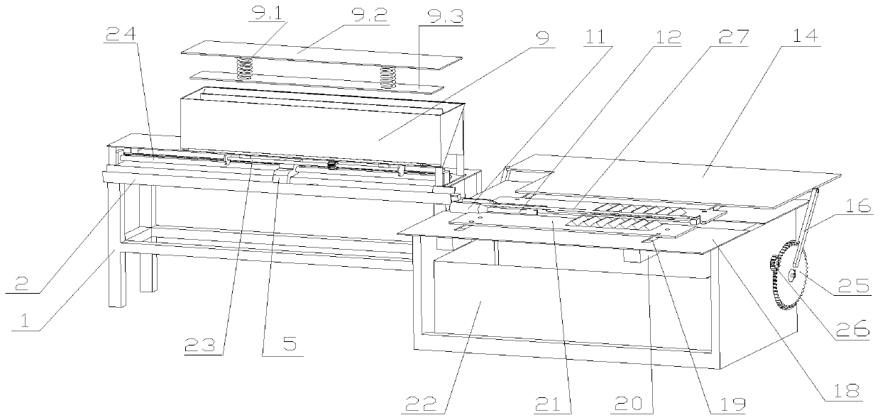
[0034] see Figure 3 ~ Figure 6 , Figure 8 ~ Figure 10 , the other structure of this embodiment is the same as that of Embodiment 1 or Embodiment 2, the difference is that the power device of the upper splint is as image 3 Shown, be that driving gear 26 and toothed disc 25 are installed on the wall of collection box 22 in series, driving gear 26 is meshed with toothed disc 25 and connected, and upper splint strut 16 is installed on the toothed disc 25.
[0035] The working process of the present invention is as follows:
[0036] 1) if figure 1 , figure 2 , Figure 4 , Figure 5 As shown, the ingredients are put into the ingredient tank 13, and the upper splint strut 16 is pulled by the upper splint power device 17 (such as an air cylinder, hydraulic cylinder or electric device) to drive the upper splint 14 downward, and the upper and lower splints engage and fix the ingredients; or image 3 As shown, the driving gear 26 rotates, driving the splint 25 to rotate, and th...
PUM
 Abstract
Description
Claims
Application Information
 - R&D
- Intellectual Property
- Life Sciences
- Materials
- Tech Scout
- Unparalleled Data Quality
- Higher Quality Content
- 60% Fewer Hallucinations
Browse by: Latest US Patents, China's latest patents, Technical Efficacy Thesaurus, Application Domain, Technology Topic, Popular Technical Reports.
© 2025 PatSnap. All rights reserved.Legal|Privacy policy|Modern Slavery Act Transparency Statement|Sitemap|About US| Contact US: help@patsnap.com


