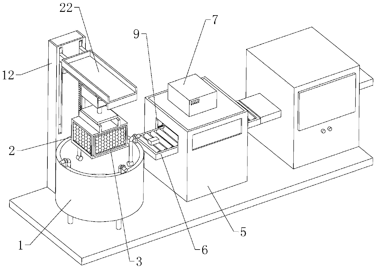
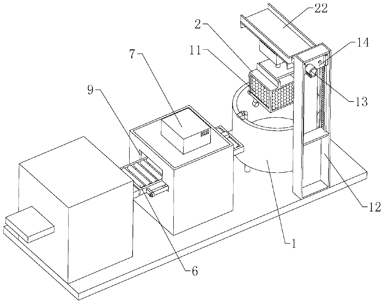
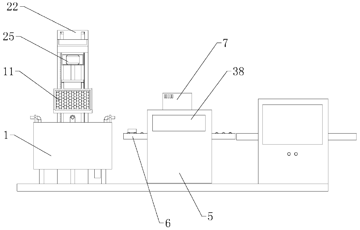
Paint-spraying die surface treatment device in toy production

A technology for surface treatment devices and molds, which is applied in spraying devices, liquid spraying devices, spray booths, etc., and can solve problems such as difficult cleaning, affecting the process, and large loss of cleaning agents.

Active Publication Date: 2020-03-17
云和县鲁祥玩具经营部
View PDF5 Cites 5 Cited by
  • Summary
  • Abstract
  • Description
  • Claims
  • Application Information

AI Technical Summary

Problems solved by technology

[0002] The painting mold is to realize the positioning of toy products in the normal production process, so as to ensure the quality and effect of toy coloring. However, in actual operation, the surface of the mold is prone to residual paint, and the mold needs to be cleaned repeatedly. At the same time, due to the surface area of ​​the mold There is a lot of oil. When cleaning the mold, the loss of cleaning agent is large, and it is not easy to clean. In the cleaning process of the spray painting mold, the surface of the spray painting mold is cleaned first, and the cleaned spray mold is then dried, and then dried. The final spraying mold is sprayed with fluororesin coating and then sent to the dryer to make the fluororesin coating solidify on the surface of the spraying mold, and then it is cooled by a cooling machine. When cleaning the spraying mold, it is generally done manually using a water gun. Cleaning treatment, manual operation is time-consuming and laborious, which affects the follow-up process, and it is not easy to spray the fluororesin coating evenly on the spraying mold, which affects the quality of the later use of the spraying mold. Therefore, we propose a method for spraying molds in toy production. surface treatment device in order to solve the problems raised above

Method used


Image

  • Paint-spraying die surface treatment device in toy production
  • Paint-spraying die surface treatment device in toy production
  • Paint-spraying die surface treatment device in toy production

Examples


Embodiment Construction

[0029] The technical solutions of the present invention will be further described below in conjunction with the accompanying drawings and through specific implementation methods.

[0030] Wherein, the accompanying drawings are only for illustrative purposes, showing only schematic diagrams, rather than physical drawings, and should not be construed as limitations on this patent; in order to better illustrate the embodiments of the present invention, some parts of the accompanying drawings will be omitted, Enlargement or reduction does not represent the size of the actual product; for those skilled in the art, it is understandable that certain known structures and their descriptions in the drawings may be omitted.

[0031] In the drawings of the embodiments of the present invention, the same or similar symbols correspond to the same or similar components; , "inner", "outer" and other indicated orientations or positional relationships are based on the orientations or positional ...


PUM


Abstract

The invention relates to the technical field of paint-spraying die surface treatment in toy production, and specifically relates to a paint-spraying die surface treatment device in toy production. Thepaint-spraying die surface treatment device in toy production comprises a drying machine, a cooling machine, a cleaning mechanism and a coating mechanism, wherein the cleaning mechanism and the coating mechanism are arranged in a manner of linear distribution; the cleaning mechanism comprises a cleaning tank, a lifting assembly, a horizontal movement assembly and an accommodating net box used foraccommodating a die; a hinge door is arranged at one end of the accommodating net box; a plurality of water guns are arranged in the cleaning tank; the coating mechanism comprises a coating box, a transfer conveyer, a liquid-spraying machine, and a guide spraying assembly; a charge port and a discharge port are formed in the two ends of the coating box separately; the guide spraying assembly comprises a liquid-spraying head capable of moving in an arc shape; and one end of the liquid-spraying head communicates with the liquid-spraying machine. The equipment is capable of automatically cleaning engine oil on the paint-spraying die, and uniformly spraying a fluororesin coating material on the paint-spraying die, so that the later-period use quality of the paint-spraying die is improved.

Description

technical field [0001] The invention relates to the technical field of surface treatment of spray paint molds in toy production, in particular to a surface treatment device for paint spray molds in toy production. Background technique [0002] The painting mold is to realize the positioning of toy products in the normal production process, so as to ensure the quality and effect of toy coloring. However, in actual operation, the surface of the mold is prone to residual paint, and the mold needs to be cleaned repeatedly. At the same time, due to the surface area of ​​the mold There is a lot of oil. When cleaning the mold, the loss of cleaning agent is large, and it is not easy to clean. In the cleaning process of the spray painting mold, the surface of the spray painting mold is cleaned first, and the cleaned spray mold is then dried, and then dried. The final spraying mold is sprayed with fluororesin coating and then sent to the dryer to make the fluororesin coating solidify ...

Claims


Application Information

Patent Timeline
Patent Type & Authority Applications(China)
IPC IPC(8): B05B16/20B05B16/40B05B13/02B05B14/40B05B15/55B08B3/02
CPCB05B9/01B05B13/02B05B13/04B08B3/022B08B13/00B05B15/68B05B16/20
Inventor 吕丽娅
Owner 云和县鲁祥玩具经营部
Why Eureka
Try Eureka