
Lifting platform for a wind power tower

A technology for lifting platforms and towers, applied in the field of lifting platforms, can solve the problems of limited construction scope, damage to the outer wall of the tower, shaking of the hanging basket, etc., and achieve the effect of high stability

Active Publication Date: 2020-11-17
SHANDONG KINGELEVATOR GRP CO LTD
View PDF5 Cites 0 Cited by
  • Summary
  • Abstract
  • Description
  • Claims
  • Application Information

AI Technical Summary

Problems solved by technology

The hanging basket is only fixed and lifted by safety ropes when in use, so the hanging basket is very vulnerable to the influence of the wind during use. When the wind is strong, the hanging basket will shake greatly and seriously affect the work safety of construction workers. Affected by the weather, construction workers can only choose to carry out construction when the weather is good and the wind is small or there is no wind.
The hanging basket is also very easy to collide with the outer wall of the tower tube during use, causing damage to the outer wall of the tower tube, which is very inconvenient to use. The hanging basket cannot rotate around the tower tube during use, so during construction, the scope of construction It will be limited, requiring multiple construction workers to work simultaneously in different hanging baskets to carry out construction around the outer circumference of the tower, wasting a lot of manpower and material resources

Method used


Image

  • Lifting platform for a wind power tower
  • Lifting platform for a wind power tower
  • Lifting platform for a wind power tower

Examples


Embodiment Construction

[0017] In order to make the objectives, technical solutions, and advantages of the embodiments of the present invention clearer, the technical solutions in the embodiments of the present invention will be described clearly and completely in conjunction with the accompanying drawings in the embodiments of the present invention. Obviously, the described embodiments It is a part of the embodiments of the present invention, not all the embodiments. Based on the embodiments of the present invention, all other embodiments obtained by those of ordinary skill in the art without creative work shall fall within the protection scope of the present invention.

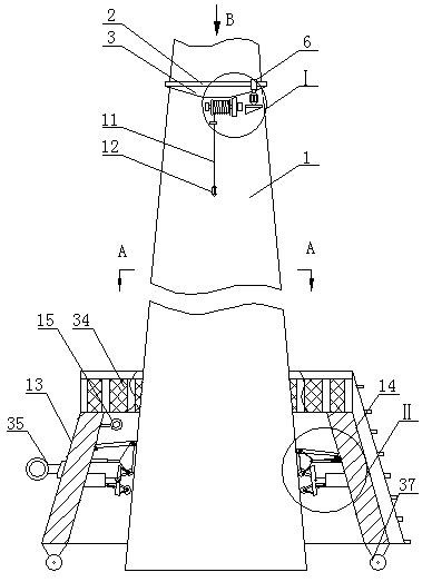
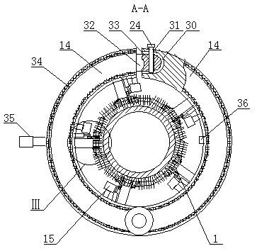
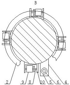
[0018] A lifting platform for a wind power generation tower, as shown in the figure, includes a turbine 2, which is mounted on the top of the outer circumference of the tower 1 through a bearing, a first bevel gear 3 is fixedly mounted on the bottom surface of the turbine 2, and a first bevel gear 3 is set On the outer circumference o...


PUM


Abstract

A lifting platform for a wind power generation tower barrel comprises a turbine, wherein the turbine is installed at the top of the outer periphery of the tower barrel through a bearing, a first bevelgear is fixedly installed on the bottom surface of the turbine, a third rotating shaft is fixedly installed at the end part of a telescopic rod, the same pulley is installed on an outer periphery bearing of the third rotating shaft, one end of a tension spring is fixedly installed at the lower part of the other side of a baffle, the other end of the tension spring is fixedly connected with the bottom of the fixed end of an electric push rod, the other end of a second annular sleeve is provided with a plurality of grooves, a plurality of first screw holes are formed in the periphery of the second annular sleeve, the first screw holes communicate with the interiors of the grooves, a plurality of clamping blocks are fixedly installed at the other end of a first arc-shaped sleeve, the clamping blocks can be positioned in the corresponding grooves at the same time, second screw holes are formed in the front of the clamping blocks, the center lines of the second screw holes can be collinearwith the center lines of the corresponding first screw holes, and bolts are jointly installed on each first screw hole and the corresponding second screw hole; and protection devices are arranged onthe top surfaces of the first arc-shaped sleeve and a second arc-shaped sleeve.

Description

Technical field [0001] The invention belongs to the field of lifting platforms, in particular to a lifting platform for wind power generation towers. Background technique [0002] Wind power equipment needs frequent inspection and maintenance to prevent damage to the wind power equipment. When the construction personnel inspect or maintain the wall of the wind power generation equipment, they need to use a lifting device to perform construction work on the outside of the tower. Most of the existing lifting devices are hanging baskets. The gondola is only fixed and lifted by safety ropes during use, so the gondola is very susceptible to wind during use. When the wind is strong, the gondola shakes greatly and seriously affects the work safety of the construction personnel. The impact of the weather The construction workers can only choose when the weather is good and the wind is small or there is no wind. The hanging basket is also very easy to collide with the outer wall of the...

Claims


Application Information

Patent Timeline
Patent Type & Authority Patents(China)
IPC IPC(8): B66F11/04B66D1/12B66D1/14F03D80/50F03D80/55F03D13/20
CPCB66D1/12B66D1/14B66D2700/0141B66D2700/0183B66F11/04F03D13/20F03D80/50F03D80/55Y02E10/72Y02E10/728
Inventor 张务水
Owner SHANDONG KINGELEVATOR GRP CO LTD
Learn More