Hydraulic oil production method and device

A hydraulic and two-way hydraulic pump technology, which is applied in the direction of mining fluid, earthwork drilling, liquid variable capacity machinery, etc., can solve the problems of increasing oil mining costs, short service life, low work efficiency, etc., and reduce equipment investment and operation Low cost, low wear, and the effect of reducing oil production costs

Inactive Publication Date: 2009-06-10
李莉 +1
View PDF5 Cites 6 Cited by
  • Summary
  • Abstract
  • Description
  • Claims
  • Application Information

AI Technical Summary

Problems solved by technology

This not only increases the cost of oil extraction, but also lowers the extraction efficiency
In addition, due to its structural reasons, the traditional pumping unit has low working efficiency, serious wear of moving parts, short service life and high failure rate, resulting in frequent downtime for maintenance
Although the traditional pumping unit has all kinds of disadvantages and unsatisfactory defects, there is no ideal mining equipment to replace it so far, which makes oil production companies use the traditional pumping unit helplessly year after year, It is still used day after day

Method used


Image

  • Hydraulic oil production method and device
  • Hydraulic oil production method and device
  • Hydraulic oil production method and device

Examples


Embodiment 1

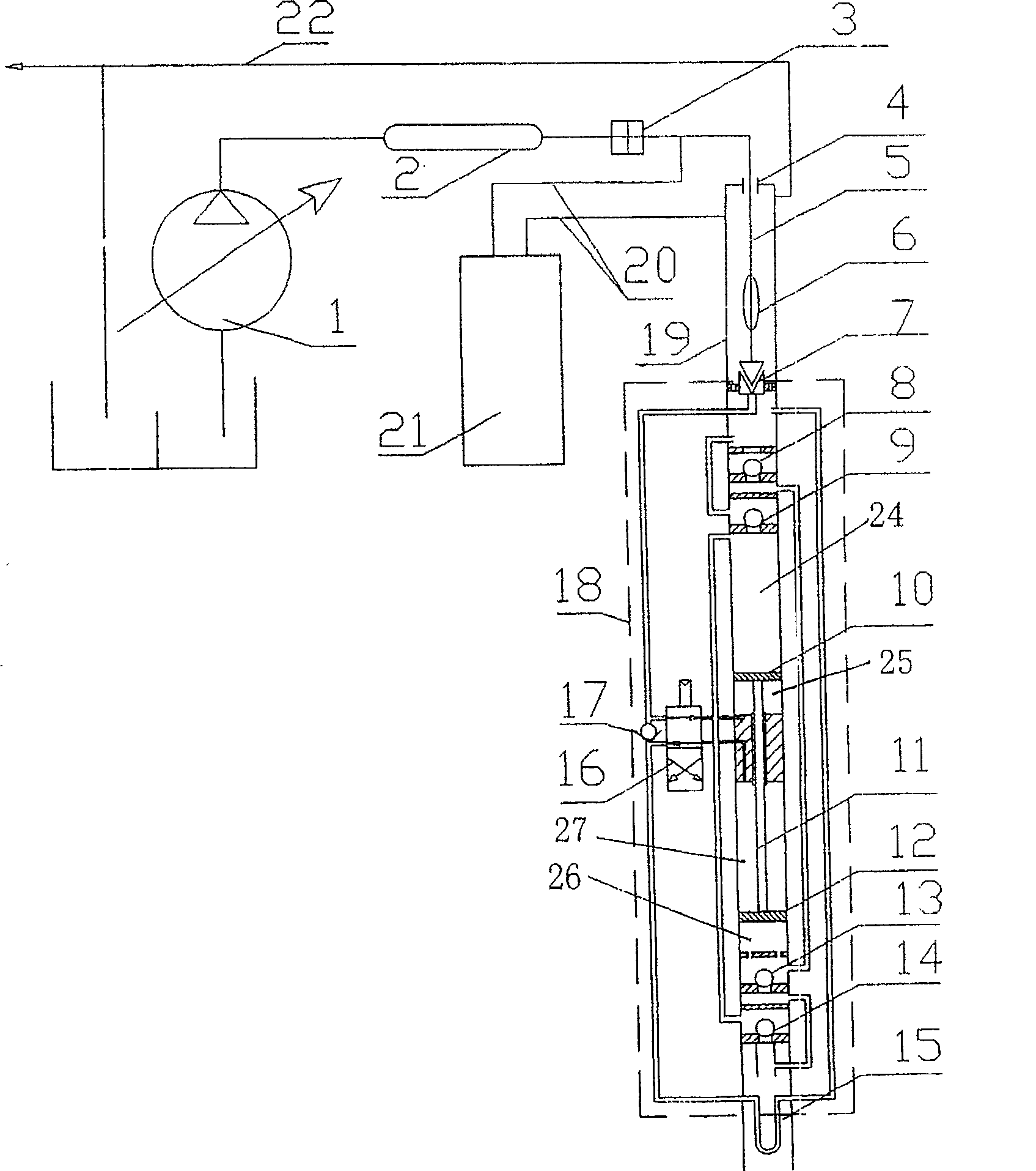
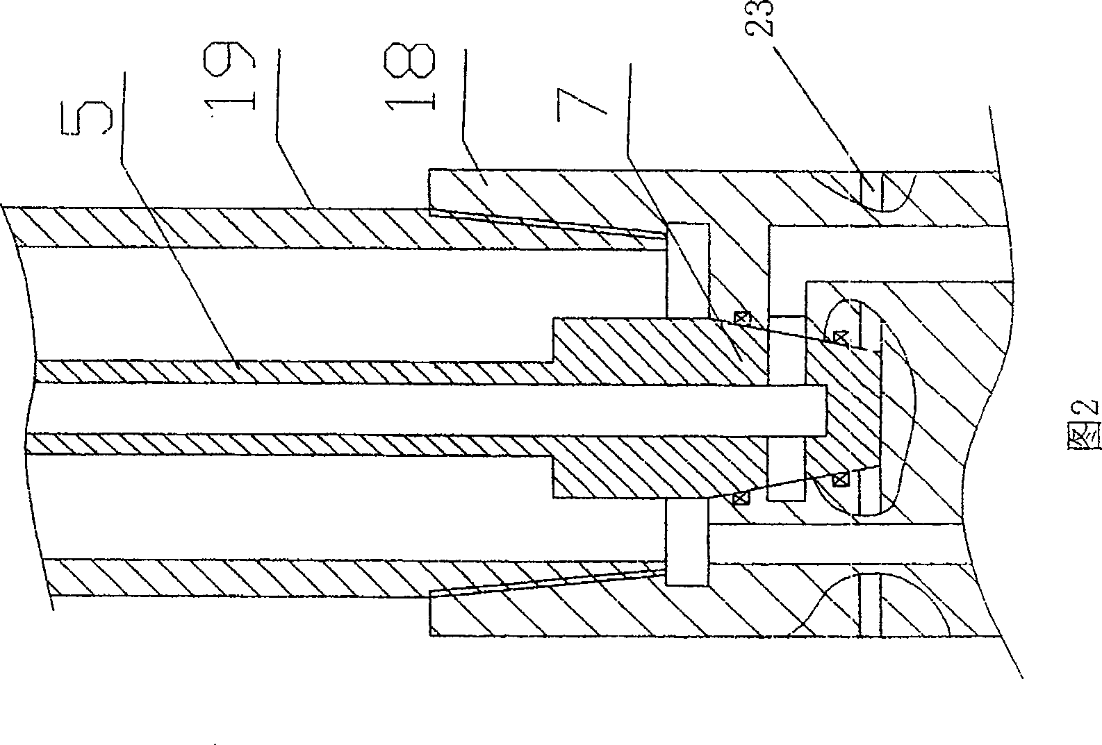
[0023] Embodiments of the present invention are described in detail in conjunction with the accompanying drawings, as figure 1 The surface hydraulic pump 1 shown is connected to the surface heater 2 through the power fluid pipeline, and the output end of the surface heater 2 is connected to the upper end of the hollow sucker rod 5 placed in the oil pipe 19 through the power fluid pipeline, the insulating pipe joint 3 The hollow sucker rod 5 is provided with an insulating centralizer 6, and the lower end is connected with the pump head of the downhole bidirectional hydraulic pump 18 through a frusto-conical hydraulic plug joint 7, as shown in Fig. 2 The two-way hydraulic pump 18 includes a pump cylinder, and a piston rod 11 with an upper piston 10 and a lower piston 12 at both ends is placed in the pump cylinder, and the two-position four-way stroke of switching the liquid channel can be realized according to the stroke positions of the upper and lower pistons 10 and 12 The rev...

Embodiment 2

[0025] No oil well electric heater and corresponding insulating pipe joint 3, insulating sealer 4 and insulating centralizer 6 are provided, and the rest is the same as that of embodiment 1.

[0026] When the present invention is in use, start the surface hydraulic pump 1 to send pressurized high-pressure water or high-pressure crude oil into the surface heater 2 along the pipeline, and the heated fluid medium carries high pressure and high temperature through the insulating pipe joint 3 and the wellhead insulating sealer 4 to enter In the hollow sucker rod 5 in the well column, and enter the upper hydraulic cylinder along the hydraulic joint 7 at the bottom of the hollow sucker rod 5, the power fluid pipeline, and a passage of the stroke reversing valve 16 in the two-way hydraulic pump assembly 18 25 makes it a high-pressure chamber and pushes the upper piston 10 upward, the cavity capacity of the upper pump chamber 24 becomes smaller and the pressure rises, and the crude oil ...


PUM


Abstract

The hydraulic oil extraction device comprise a ground hydraulic power for supplying high temperature and high pressure power liquid, a ground heater, a hydraulic power pipe that connects through a hollow oil extracting pole in the oil pipe and a stroke change-over valve nested the piston rod on the dual direction hydraulic pump with the piston rod having pistons at both ends. From bottom to up of the upper pump, there exists an upper pump outlet valve and a bottom pump valve, which connect respectively with the oil pipe and the outlet of the inlet valve of the bottom pump below the bottom pump cavity. Inlet of the upper outlet valve connects with the outlet of the upper pump inlet valve under the bottom pump let valve though pipe fittings. Discharging end of the adynamia hydraulic pipe connects with one of the channel of the stroke change-over valve, and the discharging end connects with the oil pipe through the pump heating tail pipe. When the upper pump discharges oil, the bottom pump absorbs oil or vice versa. This continuous alternating circulation carries the crude oil to the ground, improves the oil extraction efficiency and it applies to all kinds of oils.

Description

technical field [0001] The invention relates to an oil extraction method and equipment, in particular to a hydraulic oil extraction method and its device, which are suitable for various types of crude oil extraction in oil wells, inclined wells, horizontal wells, offshore platforms and oil fields. Background technique [0002] Heavy oil occupies a certain proportion of the world's petroleum resources. This type of oil is characterized by high asphaltene and colloid content, high freezing point, and high viscosity. Therefore, it adds great difficulty to oil extraction. The distribution of heavy oil resources in my country is also very wide, accounting for more than 20% of the total land oil resources. The way to solve this difficult problem at present is to use other special equipment and measures to reduce the viscosity of the crude oil in the well string while the pumping unit is pumping oil. Such as injecting hot water, hot oil or chemical viscosity reducer into the well....

Claims


Application Information

Patent Timeline
Patent Type & Authority Patents(China)
IPC IPC(8): E21B43/00E21B43/24F04B47/00
Inventor 叶少华
Owner 李莉
Why Eureka
Try Eureka