
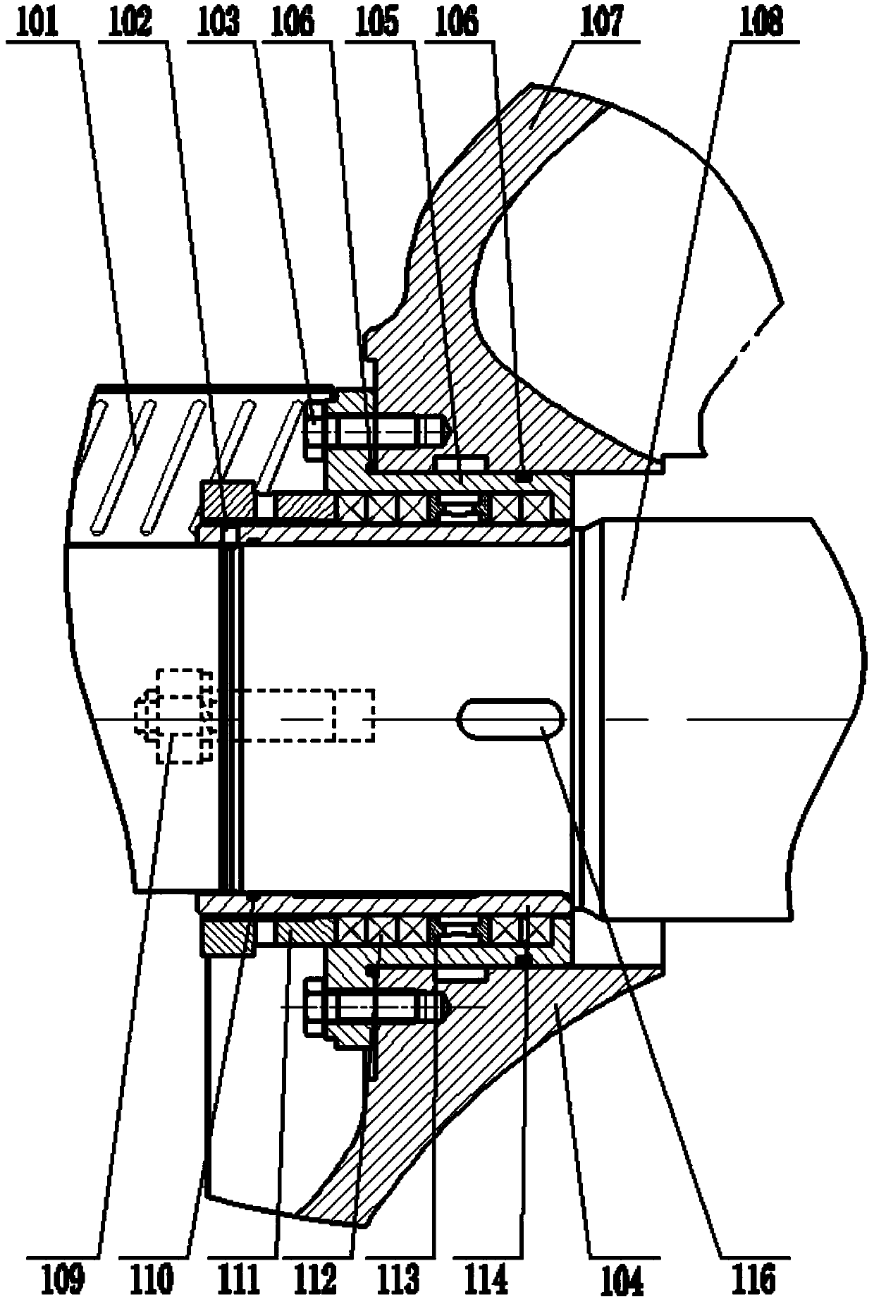
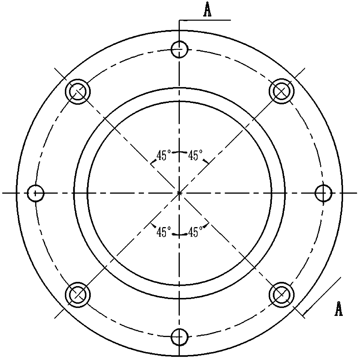
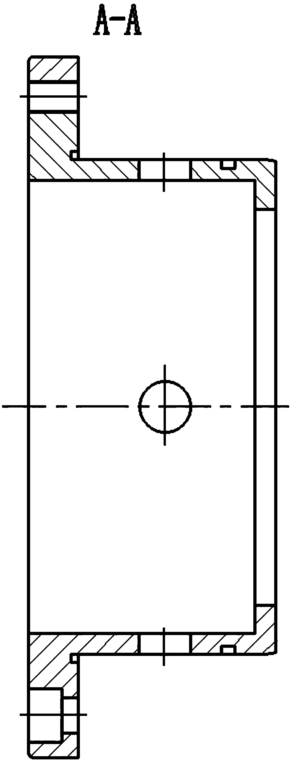
Horizontal split centrifugal pump shaft seal structure

A horizontal split, centrifugal pump technology, applied in the direction of pumps, pump components, non-variable-capacity pumps, etc., can solve the problems of complicated replacement of seals, tedious and time-consuming disassembly and maintenance, and lack of interchangeability of parts, saving replacement. Filling and maintenance costs, improvement of standardization and modularity, convenient disassembly and maintenance

Inactive Publication Date: 2020-03-17
WILO CHINA
View PDF6 Cites 0 Cited by
  • Summary
  • Abstract
  • Description
  • Claims
  • Application Information

AI Technical Summary

Problems solved by technology

[0003] There are two main types of shaft seal structure in the existing horizontal split centrifugal pump: packing seal and mechanical seal. The parts of the two seal types are not interchangeable. It is very complicated and costly for the user to replace the seal on site.
In addition, in the existing packing shaft seal method, the packing shaft sleeve has poor sealing performance and often has the phenomenon of inaccurate positioning and axial movement. The packing seal needs to be replaced regularly. The existing packing gland is an integral structure, which requires It is disassembled from the shaft head, so the disassembly and maintenance are cumbersome and time-consuming, and the maintenance cost is high

Method used


Image

  • Horizontal split centrifugal pump shaft seal structure
  • Horizontal split centrifugal pump shaft seal structure
  • Horizontal split centrifugal pump shaft seal structure

Examples


Embodiment Construction

[0036] The technical solutions of the present invention will be further described in detail below through the accompanying drawings and embodiments.

[0037] The embodiment of the present invention relates to the provided horizontal split centrifugal pump shaft seal structure, which makes the horizontal split centrifugal pump shaft seal assembly more convenient, the sealing method is interchangeable, and the design of the universal seal greatly improves the standardization and modularization of parts It reduces the cost of parts management, more accurate positioning, good sealing performance, and ensures that the pump set with the application of this application level split centrifugal pump shaft seal structure has good operating hydraulic performance and operating stability, and has low vibration and noise test parameters , Easy to disassemble and maintain.

[0038] It can be understood that the specific embodiments described below are only used to explain the present invention, b...


PUM


Abstract

The embodiment of the invention relates to a horizontal split centrifugal pump shaft seal structure. The horizontal split centrifugal pump shaft seal structure comprises a pump shaft, a pump cover, apump body, a universal seal body, a packing shaft sleeve, a packing, a packing ring and two split half-type packing glands, wherein the packing shaft sleeve is cylindrical and is sleeved on the pump shaft, the cross section of the universal seal body is of an inverted convex shape and is mounted on the pump cover and the pump body through a plurality of connecting bolts, the packing is arranged between the packing shaft sleeve and the universal sealing body, one end of the packing abuts against the universal sealing body, the packing ring is arranged between the packing shaft sleeve and the universal sealing body and is arranged in the packing, the two half-type packing glands are butted and mounted between the packing shaft sleeve and the universal sealing body, and the half-type packingglands are abutted against the other end of the packing. According to the horizontal split centrifugal pump shaft seal structure, the assembling is more convenient, the sealing mode is good in interchangeability, and the part management cost is reduced.

Description

technical field [0001] The invention relates to the technical field of centrifugal pump equipment, in particular to a shaft seal structure of a horizontal split centrifugal pump. Background technique [0002] The horizontal split centrifugal pump has the characteristics of large flow and relatively stable operation, and is widely used in municipal water conservancy, iron and steel metallurgy, water plants, power plants and other fields. As an important core part of the horizontal split pump, the pump body and the pump cover adopt the structural form of the horizontal split, and the ensuing sealing of the split surface and the sealing of the shaft ends on both sides are good or bad, which has a great impact on the entire pump. The hydraulic performance and comprehensive operation performance of the group have a crucial influence. Therefore, the structure and form of the shaft end seal are the key factors to ensure the efficient and stable operation of the pump set. [0003]...

Claims


Application Information

Patent Timeline
IPC IPC(8): F04D29/10F04D29/12F04D29/62
CPCF04D29/106F04D29/126F04D29/628
Inventor 支发林李广一康蕾蕾
Owner WILO CHINA
Learn More