Bus power transmission system and bus pipeline supporting device thereof

A technology for bus ducts and supporting devices, which is applied in the direction of fully enclosed bus devices, bus installation, switchgear, etc., can solve the problems of easy damage stability of bus ducts, easy damage of bus ducts, etc. The effect of stress damage

Active Publication Date: 2020-03-17
PINGGAO GRP +3
View PDF12 Cites 3 Cited by
  • Summary
  • Abstract
  • Description
  • Claims
  • Application Information

AI Technical Summary

Problems solved by technology

[0003] The object of the present invention is to provide a bus pipe support device to solve the problem that the bus pipe is easily damaged due to thermal displacement in the prior art; in addition, the purpose of the present invention is to provide a bus power transmission system using the device to Solve the problem of poor stability of the busbar power transmission system in the prior art due to the thermal displacement of the busbar pipeline and easy damage

Method used


Image

  • Bus power transmission system and bus pipeline supporting device thereof
  • Bus power transmission system and bus pipeline supporting device thereof
  • Bus power transmission system and bus pipeline supporting device thereof

Examples


specific Embodiment 2

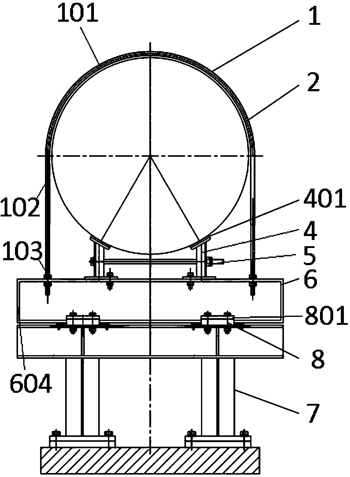
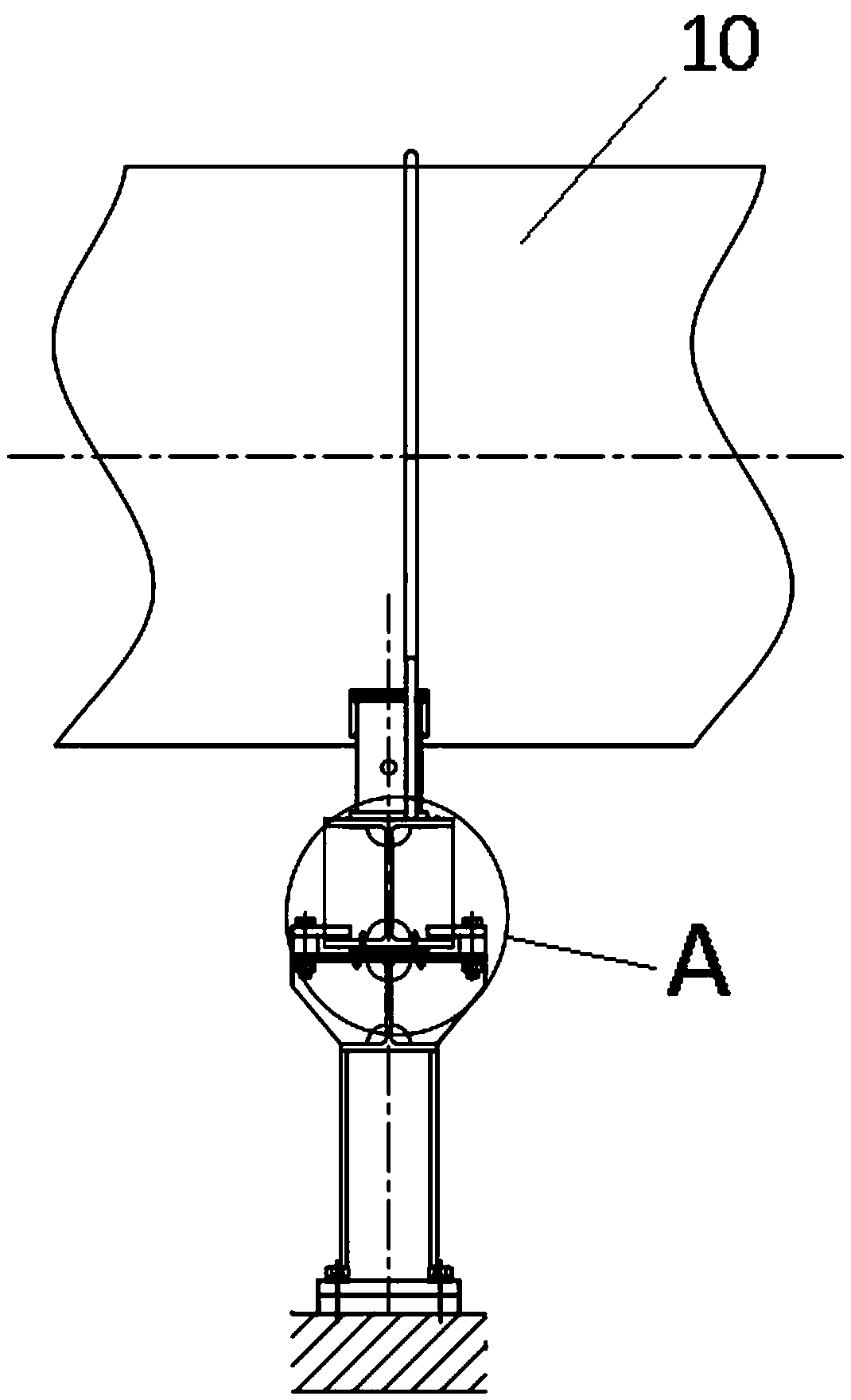
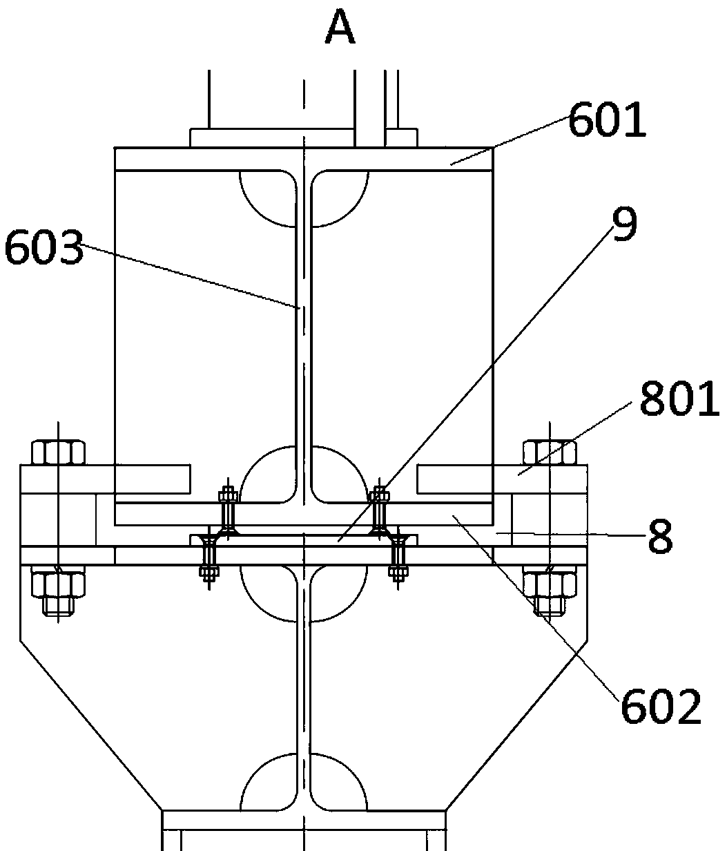
[0052] Specific embodiment 2 of the busbar power transmission system of the present invention. In this embodiment, the structure of the busbar power transmission system is simplified. In this embodiment, the busbar power transmission system includes a busbar duct and a busbar duct supporting device supporting the busbar duct. The busbar duct supporting device It includes a support seat for supporting the bus duct, on which a bus assembly structure is provided, and the bus assembly structure has a structure for the bus duct to pass through for sliding fit with the bus duct along the axial direction of the bus duct and along the radial direction of the bus duct. The busbar slideway that fits in the direction of the busbar duct. By setting the busbar assembly structure, the busbar duct can slide along the axis of the busbar duct when thermal displacement occurs, so as to avoid damage to the busbar duct and the supporting seat.

[0053] Specific embodiment 3 of the busbar power tr...

specific Embodiment 9

[0059] Embodiment 9 of the bus power transmission system of the present invention, as a further optimization of any one of Embodiments 2 to 7, the bus assembly structure further includes a buffer structure arranged between the bus duct and the bus slideway. Certainly, no buffer structure may be provided in other embodiments.

[0060] The specific embodiment 10 of the bus power transmission system of the present invention, as a further optimization of the specific embodiment 9, the buffer structure is a heat-shrinkable sheath arranged between the bus duct and the bus slideway. Certainly, in other embodiments, the buffer structure may also be a rubber pad provided on the bus bar clamp.

[0061] The specific embodiment 11 of the busbar power transmission system of the present invention, as a further optimization of any one of the specific embodiments 2 or 3, the support seat includes a seat body and a sliding seat slidingly assembled on the seat body, and the busbar assembly stru...

specific Embodiment 20

[0070] The specific embodiment 20 of the bus power transmission system of the present invention differs from the specific embodiment 1 of the bus power transmission system of the present invention only in that the supporting seat is an integrated tubular structure.

[0071] The specific embodiment 21 of the bus power transmission system of the present invention differs from the specific embodiment 1 of the bus power transmission system of the present invention only in that the slider is cylindrical and extends towards the radial direction of the bus duct, and the slide rail is cylindrical The sliding block is matched with the cylindrical sliding rail, and the two side walls of the notch of the cylindrical sliding rail are slidably matched with the web.


PUM


Abstract

The invention provides a bus power transmission system and a bus pipeline supporting device thereof, and belongs to the field of power equipment. The bus pipeline supporting device comprises a supporting seat used for supporting a bus pipeline, the supporting seat is provided with a bus assembling structure, and the bus assembling structure is provided with a bus slideway which allows the bus pipeline to penetrate through, is used for being in sliding fit with the bus pipeline in the axial direction of the bus pipeline and is in limiting fit with the bus pipeline in the radial direction of thebus pipeline. When the bus pipeline moves along the axial direction, the bus pipeline slides in the bus slideway, so that the bus pipeline and the supporting seat are prevented from being damaged bystress, and the problem that the bus pipeline is easy to damage when generating thermal displacement in the prior art is solved.

Description

technical field [0001] The invention relates to a busbar power transmission system and a busbar pipe support device thereof. Background technique [0002] In recent years, with the rapid development of economy and industry, the demand for installed capacity of power grids at home and abroad has gradually increased. As a transmission form that may replace overhead lines, power cables and wall bushings, gas-insulated metal-enclosed transmission lines (GIL) are used in It has been increasingly widely used in long-distance, large-capacity and special environmental conditions. When the GIL bus duct is used for long-distance and large-capacity power transmission, the axial deformation caused by the thermal expansion and contraction effect is relatively obvious, and the stress will pose a hazard to the safe operation of the GIL bus duct. However, if the support of the bus duct is fully rigidly connected to the GIL shell, the shell will be restrained by the support when it deforms ...

Claims


Application Information

Patent Timeline
Patent Type & Authority Applications(China)
IPC IPC(8): H02G5/06H02B13/00
CPCH02G5/061H02B13/005
Inventor 叶三排柏长宇金光耀郭煜敬戴锋姚永其王志刚裴涛李丽娜
Owner PINGGAO GRP
Why Eureka
Try Eureka