Traction and suspension system

A traction system, suspension technology, applied in the direction of suspension, elastic suspension, transportation and packaging to achieve the effect of improving initial adhesion

Pending Publication Date: 2020-03-17
德萨动力有限公司
View PDF8 Cites 0 Cited by
  • Summary
  • Abstract
  • Description
  • Claims
  • Application Information

AI Technical Summary

Problems solved by technology

In addition, people will encounter difficulties in integrating the system in WO2015155670 into the existing framework structure

Method used


Image

  • Traction and suspension system

Examples


Embodiment Construction

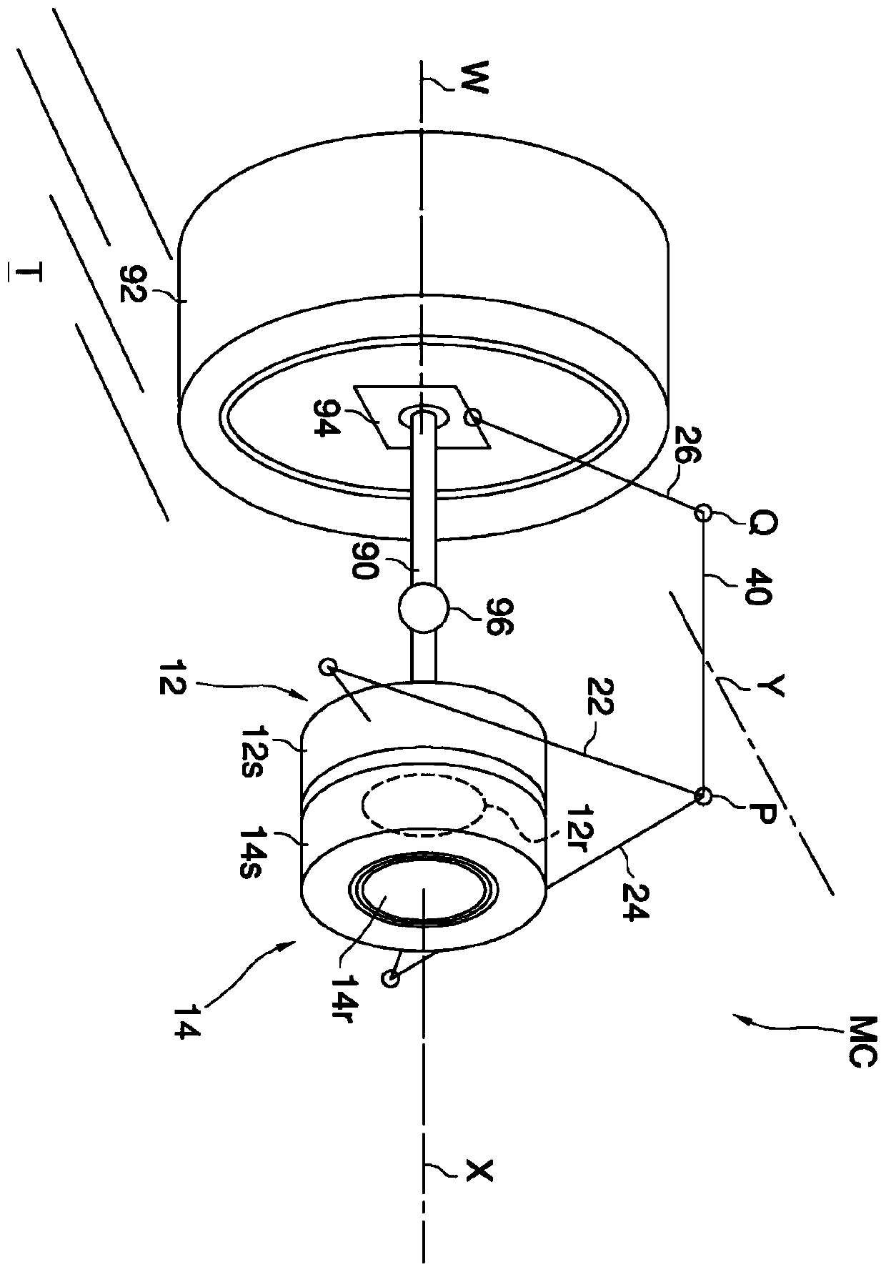
[0065] The illustrated system MC is used to rotate a propulsion element in the form of a wheel. By rolling over the terrain T, the wheels move an associated vehicle (not shown). For example the system MC is replicated on all wheels of the vehicle.

[0066] System MC comprises two identical rotary electric motors 12 , 14 capable of rotating a wheel 92 by means of a shaft 90 .

[0067] The two electric motors 12, 14 are formed by respective stators 12s, 14s and respective rotors 12r, 14r.

[0068] The rotors 12r, 14r are coaxial and have a common axis of rotation denoted X. The X-axis is fixed relative to the frame of the vehicle, for example by mounting the rotors 12r, 14r and / or the shaft 90 on ball bearings (not shown) with rings integral to the frame.

[0069] Each stator 12s, 14s is connected to a respective rigid arm 22, 24, and the arms 22, 24 are connected to a common point P external to the motors 12, 14.

[0070] Point P belongs to or is connected to the end of lev...


PUM


Abstract

A suspension and traction system is described for a vehicle equipped with a frame and a propulsive element (92) through rolling on the ground adapted to move the vehicle relative to the ground. Thereare two rotary electric motors ( 12, 14), which are mounted to impart in the same direction an angular torque to the propulsive element in order to propel the vehicle on the ground, are controllable independently of each other and each comprise a stator (12s, 14s) and a rotor ( 12r, 14r). The two rotors ( 12r, 14r) are coupled to the propulsive element (92) for transferring to it rotary motion through a transmission shaft (90), and have a common rotation axis (X) which is fixed relative to the vehicle's frame; while the stators ( 12s, 14s) are controllable to rotate about the respective rotorindependently of each other, and rigidly connected substantially to a same point (P), external to the motors, on which there can be exerted a thrust determined by the coordinated angular displacementof the stators about the respective rotors. A transmission (26) for transmitting the thrust generated on said point (P) to the propulsive element completes the system. The system guarantees integratedsuspension and traction.

Description

technical field [0001] The present invention generally relates to traction and suspension systems, particularly in electric vehicles. Background technique [0002] In the latest generation of electric vehicles, the traction has been set directly into the wheels, so the weight of the wheels increases (about 30 kg), while the weight of the whole vehicle can be even lower. Since the spring force of the suspension is roughly the weight of the vehicle divided by the number of wheels, the dynamic behavior of the wheels is less controlled because the suspension has to act on a larger mass. Some manufacturers restore stability by adding linear actuators alongside (or in place of) the suspension, but by adding complexity (especially control complexity) when the initial goal was and will always be to reduce weight It doesn't seem to be enough to solve this problem. [0003] A different solution is proposed in WO2015155670, which not only teaches how to apply propulsion torque to the...

Claims


Application Information

Patent Timeline
Patent Type & Authority Applications(China)
IPC IPC(8): B60G3/20
CPCB60G3/20B60G2300/50B60G2200/18B60G2202/25B60G2204/421B60G2206/10B60K7/0007
Inventor A·吉罗托
Owner 德萨动力有限公司
Why Eureka
Try Eureka