
Microfluidic device and method for loading fluid in microfluidic device

A microfluidic, fluid technology, used in chemical instruments and methods, fluid controllers, laboratory utensils, etc., that can solve problems such as methods for measuring or controlling input volumes that are not described

Active Publication Date: 2021-12-21
SHARP LIFE SCI EU LTD
View PDF15 Cites 0 Cited by
  • Summary
  • Abstract
  • Description
  • Claims
  • Application Information

AI Technical Summary

Problems solved by technology

Related application US20100282609 (Pollack et al.; published Nov. 11, 2010) does describe a piston mechanism for the infusion of fluids, but also does not describe methods of measuring or controlling the infusion volume of such fluids

Method used


Image

  • Microfluidic device and method for loading fluid in microfluidic device
  • Microfluidic device and method for loading fluid in microfluidic device
  • Microfluidic device and method for loading fluid in microfluidic device

Examples


Embodiment Construction

[0086] Accordingly, embodiments of the present invention will now be described with reference to the drawings, wherein like reference numerals may be used to refer to like elements throughout. It should also be understood that the drawings are not necessarily to scale.

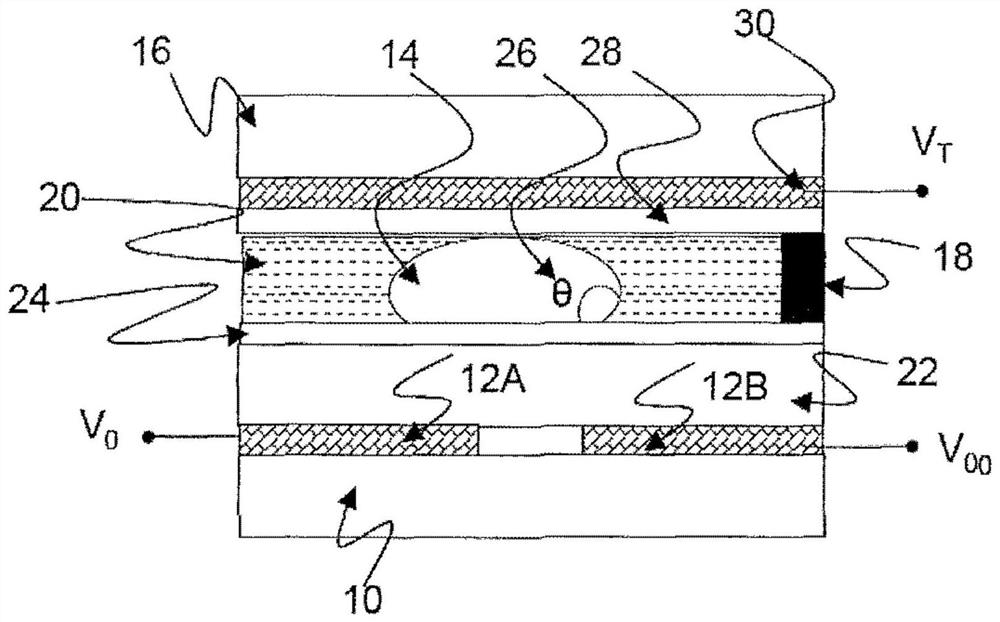
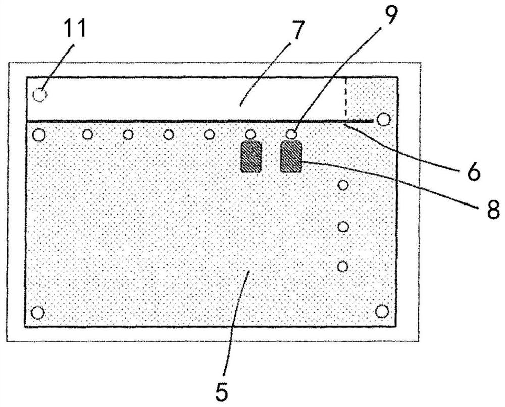
[0087] It has been recognized that although image 3 The microfluidic devices of GB 2542372 / WO 2017 / 047082 shown in Two problems may arise in (as required in some applications of this device).

[0088] exist image 3 One problem that can arise in devices that are loaded into the fluid chamber is that if the total volume of the fluids (filler fluid and working fluid) loaded into the fluid chamber is less than the total volume of the fluid chamber of the device, bubbles of air (or other exhaust fluid) will remain in the within the device. As long as the device is kept at a uniform temperature (e.g., at room temperature) and the cell gap of the device is relatively uniform, this bubble will remain in a contro...


PUM


Abstract

A microfluidic device comprising: an upper substrate and a lower substrate spaced apart so as to define a fluid chamber therebetween; a hole for introducing a fluid into the fluid chamber; and a fluid input structure, Disposed over the upper base plate and having a fluid well for receiving fluid from a fluid applicator inserted into the fluid well. The fluid well communicates with a fluid outlet disposed in the base of the fluid input structure, the fluid outlet being adjacent to the bore. The fluid well comprises a first portion, a second portion and a third portion, wherein the first portion of the well is formed with a reservoir for a fill fluid; and the second portion of the well is configured to seal against an outer surface of a fluid applicator inserted into the fluid well ground against the joint. A third portion of the well is in communication with the fluid outlet, and the diameter of the third portion at the interface between the third portion and the second portion is greater than the diameter of the second portion at the interface between the third portion and the second portion.

Description

technical field [0001] The present invention relates to a microfluidic device and to a method for loading fluid into such a device. More specifically, the present invention relates to active matrix electrowetting on dielectric (AM-EWOD) microfluidic devices. Electrowetting on dielectric (EWOD) is a known technique for manipulating fluidic droplets on an array. Active Matrix EWOD (AM-EWOD) refers to realizing EWOD in an active matrix array including transistors, for example by using thin film transistors (TFTs). Background technique [0002] Microfluidics is a rapidly expanding field that involves the manipulation and precise control of fluids on smaller scales, typically dealing with sub-microlitre volumes. Both in research and in production, there is an increasing interest in the application of microfluidics to chemical or biochemical assays and synthesis, as well as to medical diagnostics ("lab on a chip"). In the latter case, the small size of the device allows for rap...

Claims


Application Information

Patent Timeline
Patent Type & Authority Patents(China)
IPC IPC(8): B01L3/00
CPCB01L3/50273B01L2400/0427B01L3/0217B01L3/502715B01L3/502792B01L2200/027B01L2200/0605B01L2200/0673B01L2200/0689B01L2300/0816B01L2300/047B01L2300/0645B01L2300/0809
Inventor 莱斯利·安·帕里-琼斯艾马·杰恩·沃尔顿
Owner SHARP LIFE SCI EU LTD
Learn More