Long-strip-shaped injection molded part

A technology of injection molded parts and long strips, which is applied in the field of long strips of injection molded parts, can solve problems such as weak bonding, easy falling off, and inability to ensure order, and achieve high appearance quality, firm combination, and high product appearance quality Effect

Inactive Publication Date: 2020-03-20
马雪
View PDF6 Cites 0 Cited by
  • Summary
  • Abstract
  • Description
  • Claims
  • Application Information

AI Technical Summary

Problems solved by technology

[0002] The shape of the injection molded product is a long strip product, and the product is formed by two injection molding methods, the first injection of A plastic, and the second injection of another B plastic; when using a commonly used two-color injection mold to form this product, the main The problem is that it is impossible to guarantee the orderliness of the molecular arrangement of the second plastic, and to form an apparent quality with consistent molecular orientation. The second is that the bonding between the two layers of plastic is not firm and it is easy to fall off. Launched a new secondary injection molding unit

Method used


Image

  • Long-strip-shaped injection molded part
  • Long-strip-shaped injection molded part
  • Long-strip-shaped injection molded part

Examples


Embodiment Construction

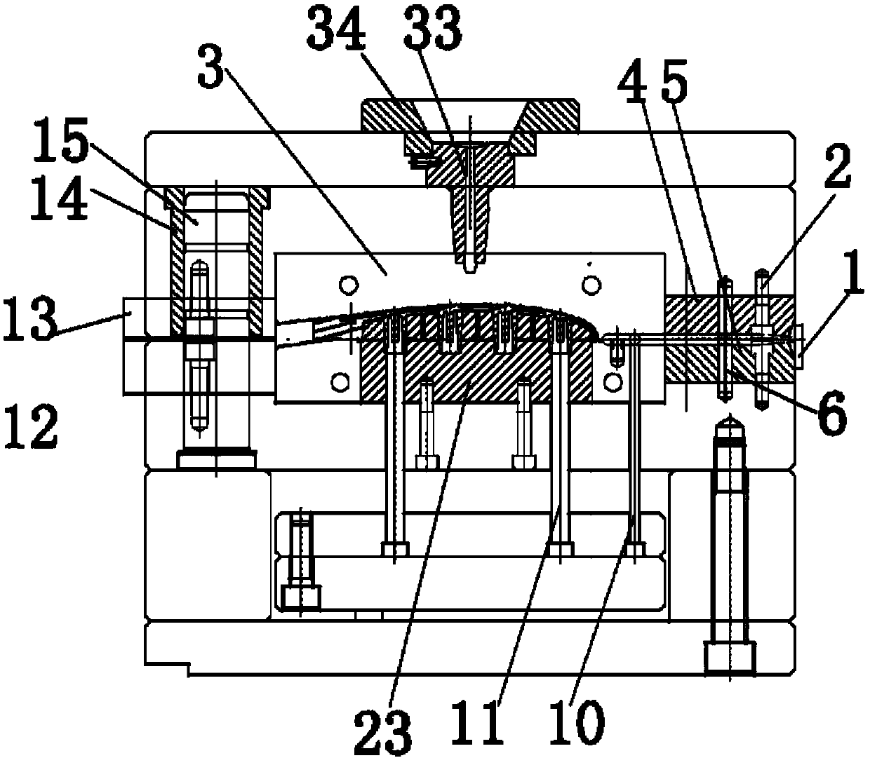
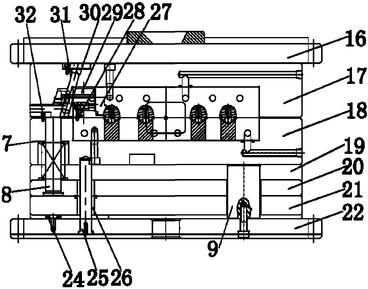
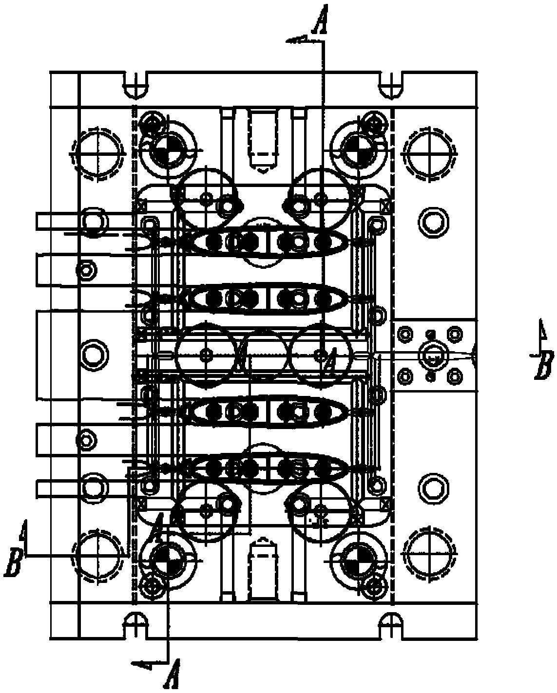
[0019] Figure 1-4 Shown is the relevant explanatory drawing of the present invention; A kind of specific embodiment of secondary injection molding mold is, as figure 2 , image 3 , Figure 4 As shown, a secondary injection molding mold includes side positioning ring 1, sprue sleeve fastening screw 2, cavity insert 3, upper half ring sprue sleeve 4, lower half ring sprue sleeve 5, gate Set positioning pin 6, reset rod spring 7, reset rod 8, support column 9, runner ejector rod 10, A rubber ejector rod 11, positioning insert 12 under the skeleton body, positioning insert 13 on the skeleton body, guide sleeve 14, Guide column 15, panel 16, fixed formwork 17, movable formwork 18, die foot 19, thimble cover plate 20, thimble push plate 21, bottom plate 22, core insert 23, garbage nail 24, thimble plate guide post 25, thimble plate Guide sleeve 26, slider head 27, slider spring 28, slider body 29, oblique guide post pressing plate 30, oblique guide post 31, slider limit screw 3...


PUM


Abstract

The invention provides a long-strip-shaped injection molded part. The long-strip-shaped injection molded part is manufactured from a secondary injection molding mold, and the secondary injection molding mold comprises parts such as a side-edge positioning ring, a sprue bush fastening screw, a mold cavity insert, an upper semi-ring sprue bush, a lower semi-ring sprue bush, a sprue bush positioningpin, a reset rod spring, a reset rod, a supporting column, a flow channel jacking rod, an A rubber jacking rod and a skeleton body lower positioning insert. Through side-edge type pouring system parts, the technical effect that it is ensured that molten material flow molecules flowing out of a main runner can be poured into a molding mold cavity without greatly changing the direction of the moltenmaterial flow molecules is achieved, and the beneficial effect that the main runner and a main flowing channel can maintain flow orientation consistency of B rubber injection molded flow molecules.

Description

technical field [0001] The invention relates to the design field of injection molded parts, in particular to a strip-shaped injection molded part. Background technique [0002] The shape of the injection molded product is a long strip product, and the product is formed by two injection molding methods, the first injection of A plastic, and the second injection of another B plastic; when using a commonly used two-color injection mold to form this product, the main The problem is that it is impossible to guarantee the orderliness of the molecular arrangement of the second plastic, and to form an apparent quality with consistent molecular orientation. The second is that the bonding between the two layers of plastic is not firm and it is easy to fall off. A new secondary injection molding unit. Contents of the invention [0003] The technical problem to be solved by the present invention is to provide a strip-shaped injection molded part, which is manufactured by a secondary ...

Claims


Application Information

Patent Timeline
Patent Type & Authority Applications(China)
IPC IPC(8): B29C45/26B29C45/16
CPCB29C45/16B29C45/2602
Inventor 不公告发明人
Owner 马雪
Why Eureka
Try Eureka