
Assembly type limiting welding platform for machining of large-scale welding part

A welding platform and welding piece technology, applied in welding equipment, auxiliary welding equipment, metal processing equipment, etc., can solve the problems of low work efficiency, high work difficulty, time-consuming and laborious, etc., and achieve the effect of improving work efficiency and simple operation.

Active Publication Date: 2020-03-24
常德市鼎鑫机械有限公司
View PDF5 Cites 2 Cited by
  • Summary
  • Abstract
  • Description
  • Claims
  • Application Information

AI Technical Summary

Problems solved by technology

[0002] In the prior art, when two large workpieces are welded, it is inconvenient to directly carry out welding operations due to the large size of the workpieces, so the welding of the existing large workpieces needs to be completed on a large welding platform, but the existing welding In the actual operation of the platform, it is very difficult to adjust the position of the base and the workpiece positioning wheel to align with the position of the weld. The adjustment process is time-consuming and laborious, and the work efficiency is low, which needs to be improved urgently

Method used


Image

  • Assembly type limiting welding platform for machining of large-scale welding part
  • Assembly type limiting welding platform for machining of large-scale welding part
  • Assembly type limiting welding platform for machining of large-scale welding part

Examples


Embodiment Construction

[0024] The present invention will be further described below in conjunction with the accompanying drawings.

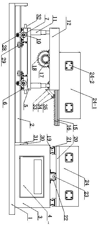
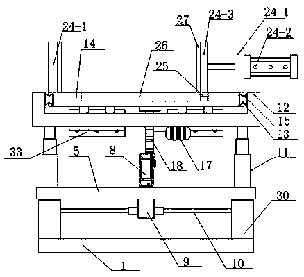
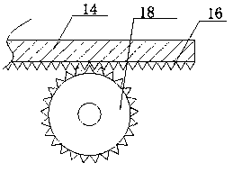
[0025] see as Figure 1-Figure 5As shown, the technical solution adopted in this specific embodiment is: the front and rear sides of the upper part of the bottom plate 1 are symmetrically fixed with an I-shaped steel track 2 by bolts, and the bottom plate 1 on the right side of the I-shaped steel track 2 is fixedly welded with a fixed platform 3 , the middle part of the fixed platform 3 is fixedly embedded with an electric control box 4, and the inside of the electric control box 4 has a power supply, a KS02Y controller and a control switch to supply power and control the electrical components inside the device; it also includes a wheel base 6, Walking wheel 7, No. 1 motor 8, No. 2 motor 17, fixed mount 12, No. 1 adjusting plate 14 and No. 2 adjusting plate 20; Each corner is fixed with a wheel base 6 by bolts, the wheel base 6 is a box body with a hollow structure wi...


PUM


Abstract

The invention discloses an assembly type limiting welding platform for machining of a large-scale welding part, and relates to the technical field of welding equipment. The assembly type limiting welding platform is characterized in that a supporting plate is arranged on the upper side of an I-shaped steel rail, wheel seats are fixedly arranged on four corners of the bottom of the supporting plate, and walking wheels are arranged inside the wheel seats in a rolling mode through axles; the upper end of a hydraulic rod is fixedly arranged on the bottom surface of a fixing frame; first sliding rails are symmetrically and fixedly arranged on the opposite surfaces of the vertical ends of the fixing frame, and a first adjusting plate is movably arranged between the first sliding rails; second sliding rails are symmetrically and fixedly arranged on the left side and the right side of the upper portion of a fixing platform, and a second adjusting plate is arranged on the upper sides of the second sliding rails; and limiting mechanisms are fixedly arranged on the upper portions of the first adjusting plate and the second adjusting plate. According to the assembly type limiting welding platform, two to-be-welded workpieces are correspondingly fixed on two adjustable platforms on the left and right, and welding joints of the two workpieces are aligned through an automatic mechanical adjusting manner, so that operation is simple, time and labor are saved, and the working efficiency is improved.

Description

technical field [0001] The invention relates to the technical field of welding equipment, in particular to an assembled limit welding platform for processing large-scale welded parts. Background technique [0002] In the prior art, when two large workpieces are welded, it is inconvenient to directly carry out welding operations due to the large size of the workpieces, so the welding of the existing large workpieces needs to be completed on a large welding platform, but the existing welding In the actual operation of the platform, it is very difficult to adjust the position of the base and the workpiece positioning wheel to align with the position of the weld. The adjustment process is time-consuming and laborious, and the work efficiency is low, which needs to be improved urgently. Contents of the invention [0003] The object of the present invention is to aim at the defects and deficiencies of the prior art, to provide an assembly-type limit welding platform for processi...

Claims


Application Information

Patent Timeline
IPC IPC(8): B23K37/04
CPCB23K37/0461
Inventor 左凯田铭莫海涛
Owner 常德市鼎鑫机械有限公司
Learn More