
Eureka
For R&D, Eureka makes reading and utilizing patents & technical documents easy.
Eureka AIR
Designed for self-driven R&D workflows. Generate viable solutions, solve complex R&D challenges, empower your innovation with AI.

Eureka Materials
Designed for material experts only. Revolutionize your material R&D, from search, analyze, to developing new materials.

TechResearch
Generate reliable direction feasibility study reports for your R&D in just a few steps.

TechSeek
Discover and master advanced knowledge NOW. Basics, ideas, possibilities, all at once.

TechMind
As an expert in R&D Theories, TechMind can generates customized viable solutions instantly.

TechRisk
Analyze your overall solution with one click, know your potential R&D risks in advance.

TechMonitor
Get weekly tech updates, stay abreast of the latest tech innovations and key insights.
Check block layout system of powder forming machine and powder forming machine
A technology of forming machine and block, which is applied in the direction of material forming presses, presses, manufacturing tools, etc., to achieve the effects of simple machine operation, reduction of production cost, and reduction of volume
- Summary
- Abstract
- Description
- Claims
- Application Information
AI Technical Summary
Problems solved by technology
Method used
Image

Examples
Embodiment 1
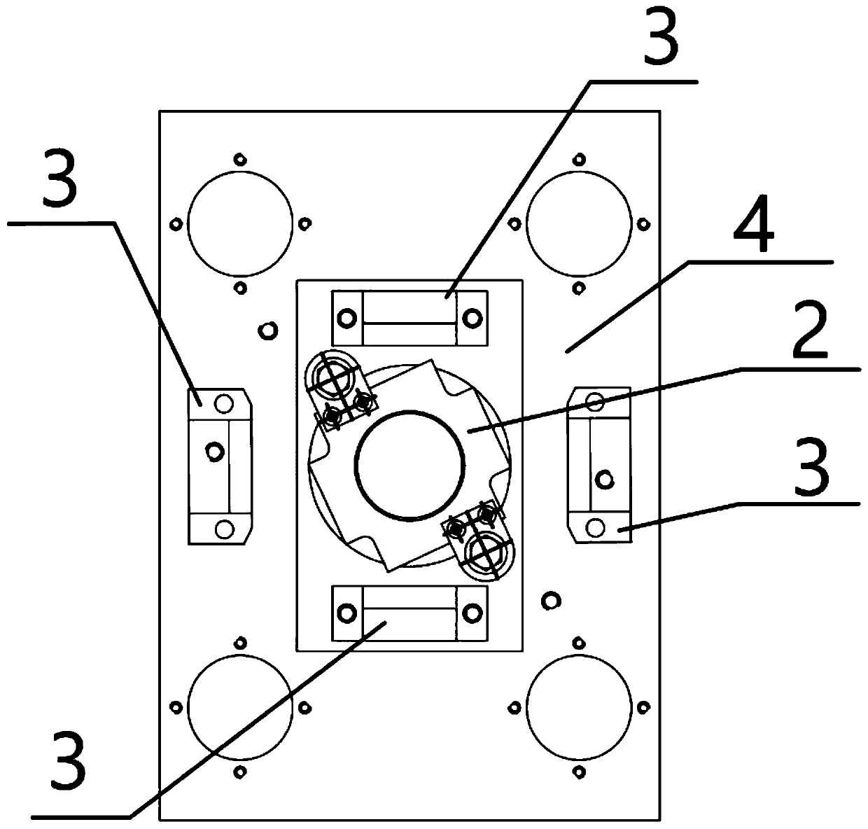
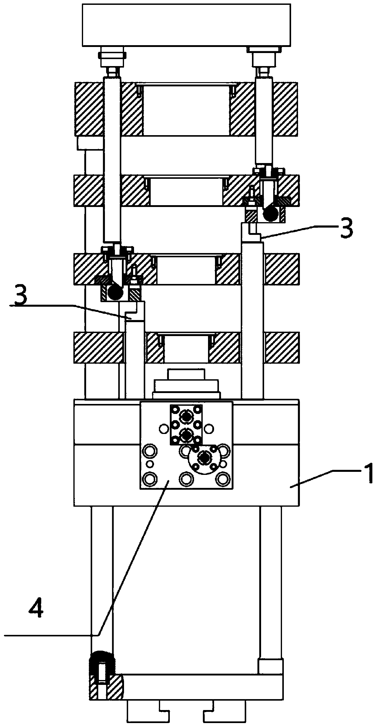
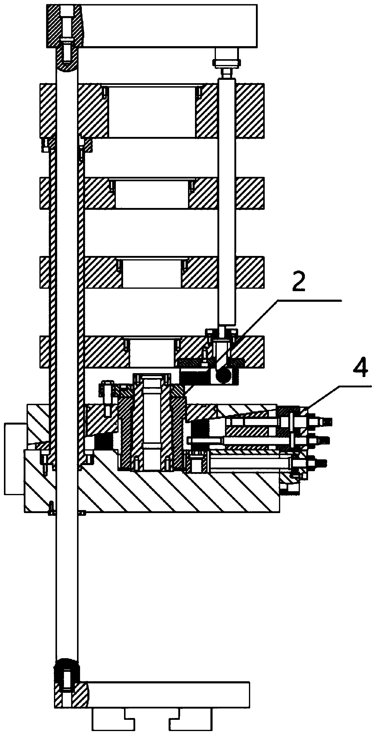
[0036] Such as figure 1 , figure 2 and image 3 As shown, the block layout system includes a base plate 1, side blocks 3, center block 2 and block forming adjustment device 4; side block 3, center block 2 and block forming adjustment device 4 are all installed on the base plate 1 The center block 2 is arranged at a position close to the geometric center of the bottom plate 1, and the side blocks 3 are arranged around the center block; the block forming adjustment device 4 corresponding to the center block 2 is arranged on a group of side blocks 3 that are arranged symmetrically Within the range of the included angle between the connecting line of the geometric center and the connecting line of the geometric center of another group of symmetrically arranged side stoppers 3 .
Embodiment 2
[0038] Such as Figure 5 , Figure 6 and Figure 7 As shown, a layout system of five lower punch blocks includes a bottom plate 1, two lower punch blocks 31, three lower punch blocks 32, four lower punch blocks 21, block forming adjustment device 4, and block forming adjustment plate 492. The block forming adjustment device 4 is installed on the block forming adjustment plate 492, the second lower punch block 31, the third lower punch block 32, the fourth lower punch block 21 and the block forming adjustment plate 492 are all installed on the base plate 1; The four lower punch blocks 21 are arranged near the geometric center of the base plate 1, the second lower punch block 31, and the third lower punch block 32 are arranged around the four lower punch blocks 21; the corresponding blocks of the four lower punch blocks 21 are formed The adjustment device 4 is arranged within the angle range between the geometric center connecting line of a group of symmetrically arranged two...
Embodiment 3
[0040] Such as Figure 4 , Figure 6 and Figure 7As shown, a layout system of five lower punch blocks includes a bottom plate 1, two lower punch blocks 31, three lower punch blocks 32, four lower punch blocks 21, block forming adjustment device 4, and block forming adjustment plate 492. The block forming adjustment device 4 is installed on the block forming adjustment plate 492, the second lower punch block 31, the third lower punch block 32, the fourth lower punch block 21 and the block forming adjustment plate 492 are all installed on the base plate 1; The four lower punch blocks 21 are arranged near the geometric center of the base plate 1, the second lower punch block 31 and the third lower punch block 32 are arranged around the four lower punch blocks 21; a group of symmetrically arranged second lower punch blocks 31 The connecting line of the geometric center of the geometric center is at a vertical angle to the connecting line of the geometric center of a group of s...
PUM
 Abstract
Description
Claims
Application Information
 - R&D Engineer
- R&D Manager
- IP Professional
- Industry Leading Data Capabilities
- Powerful AI technology
- Patent DNA Extraction
Browse by: Latest US Patents, China's latest patents, Technical Efficacy Thesaurus, Application Domain, Technology Topic, Popular Technical Reports.
© 2024 PatSnap. All rights reserved.Legal|Privacy policy|Modern Slavery Act Transparency Statement|Sitemap|About US| Contact US: help@patsnap.com