Tail vane refitting structure for refitting manned helicopter into aviation fire extinguishing device

A technology of fire extinguishing device and helicopter, which is applied to rotorcraft, motor vehicles, fire rescue and other directions, can solve the problems of unfavorable automatic flight and fire extinguishing, unfavorable maintenance and repair, slow response speed, etc., and achieves advantages of automatic flight and fire extinguishing, simple structure, Responsive effect

Pending Publication Date: 2020-03-24
STATE GRID HUNAN ELECTRIC POWER +2
View PDF3 Cites 2 Cited by
  • Summary
  • Abstract
  • Description
  • Claims
  • Application Information

AI Technical Summary

Problems solved by technology

However, for unmanned helicopters controlled by flight control computers, it will cause a response lag, and there are the following problems:
[0004] ① Under complex turbulent conditions such as smoke plume caused by on-site transmission line mountain fires, on-site ambient wind and rotor airflow, etc., the response speed is slow, and the unmanned helicopters used to extinguish the transmission line mountain fires may stay in high-temperature areas for a long time, near Dangerous areas such as line areas are not conducive to automatic flight and fire fighting;
[0006] In addition, the unmanned helicopter cabin is full of various avionics equipment, and the tail servo is placed in the cabin, which is not conducive to daily maintenance and overhaul.

Method used


Image

  • Tail vane refitting structure for refitting manned helicopter into aviation fire extinguishing device
  • Tail vane refitting structure for refitting manned helicopter into aviation fire extinguishing device
  • Tail vane refitting structure for refitting manned helicopter into aviation fire extinguishing device

Examples


Embodiment Construction

[0024] In order to facilitate the understanding of the present invention, the present invention will be described in detail below with reference to the accompanying drawings and preferred embodiments of the specification, but the protection scope of the present invention is not limited to the following specific embodiments.

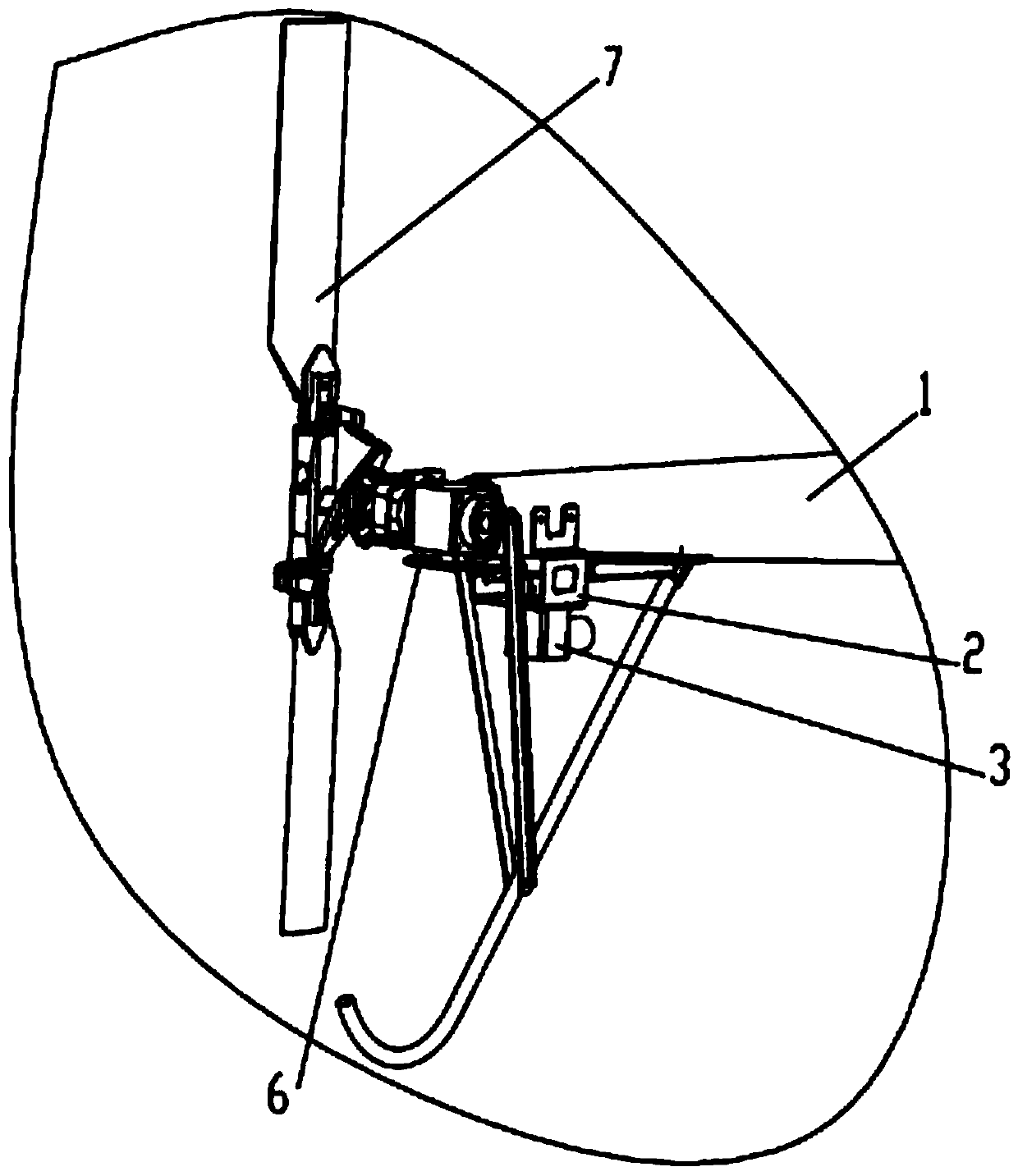
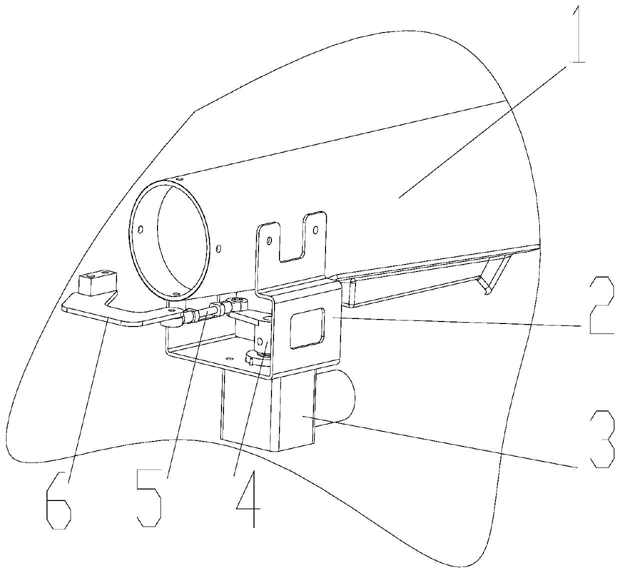
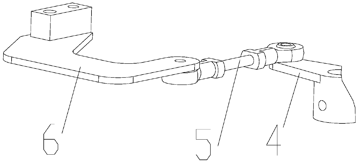
[0025] See Figure 1 ~ Figure 3 The manned helicopter of the present invention is converted into a tail rudder modification structure of an aviation fire extinguishing device, including a steering gear 3, a steering gear mounting seat 2, a steering gear rocker arm 4, and a rigid connecting rod 5. Both ends of the rigid connecting rod 5 are provided with rods End bearing, the steering gear 3 is installed outside the helicopter through the steering gear mounting seat 2 and is located vertically below the end of the helicopter tail beam 1. One end of the steering gear rocker arm 4 is fixedly connected to the output shaft of the steering gear 3. The other end of...


PUM


Abstract

The invention discloses a tail vane refitting structure for refitting a manned helicopter into an aviation fire extinguishing device. The device comprises a steering engine, a steering engine mountingseat, a steering engine rocker arm and a rigid connecting rod with rod end bearings at two ends, the steering engine is arranged below the tail end of the helicopter tail beam through a steering engine mounting seat; one end of the steering engine rocker arm is fixedly connected to an output shaft of the steering engine; the other end is connected with a rod end bearing at one end of the rigid connecting rod; a rod end bearing at the other end of the rigid connecting rod is connected with a tail rotor rocker arm of the helicopter; the steering engine rocker arm, the rigid connecting rod and the tail rotor rocker arm are horizontally arranged, the rigid connecting rod is perpendicular to the steering engine rocker arm and the tail rotor rocker arm, the steering engine rocker arm converts the angle output by a steering engine into the length, the rigid connecting rod directly acts on the tail rotor rocker arm to drive a tail rotor to achieve pitch changing, and therefore idle stroke controlled by the steering engine is avoided. The unmanned aerial vehicle is simple in structure, flight control sensitivity can be improved, automatic flight and fire extinguishing of the fire extinguishing unmanned aerial vehicle are facilitated, fire extinguishing efficiency is improved, and daily maintenance and inspection are facilitated.

Description

Technical field [0001] The invention relates to an unmanned helicopter for extinguishing mountain fires on power transmission lines, in particular to a tail rudder modification structure based on a manned helicopter modified into an aviation fire extinguishing device. Background technique [0002] Currently, unmanned helicopter technology is developing rapidly, and various unmanned helicopters are widely used in national defense, agriculture, forestry, electric power and other industries. At present, the design of unmanned helicopters generally includes two ideas; one is to redesign the drone based on actual applications. This method makes the helicopter structure reasonable, but the initial investment cost is relatively high and the risk is relatively high; the other is based on The existing manned helicopters are undergoing unmanned modification. This modification method needs to integrate the original design ideas and specific requirements of the modification, which is slightl...

Claims


Application Information

Patent Timeline
Patent Type & Authority Applications(China)
IPC IPC(8): B64C27/82A62C3/02
CPCB64C27/82A62C3/0228
Inventor 周特军吴传平李波刘毓潘碧宸
Owner STATE GRID HUNAN ELECTRIC POWER
Why Eureka
Try Eureka