Vertical jack

A kind of jack and vertical technology, which is applied in the direction of lifting device, fluid pressure actuator, servo motor assembly, etc., can solve the problems affecting the stability of the jack, the different loading speed of the three-stage piston rod, etc., and achieve strong replaceability and guarantee The effect of high service life and high precision

Pending Publication Date: 2020-03-24
CHANGSHU TONGRUN AUTO ACCESSORY
View PDF1 Cites 0 Cited by
  • Summary
  • Abstract
  • Description
  • Claims
  • Application Information

AI Technical Summary

Problems solved by technology

[0003] The problem with the above technical solution is that the three-stage piston rods have different speeds when loaded, which affects the stability of the jack during work.

Method used


Image

  • Vertical jack
  • Vertical jack
  • Vertical jack

Examples


Embodiment 1

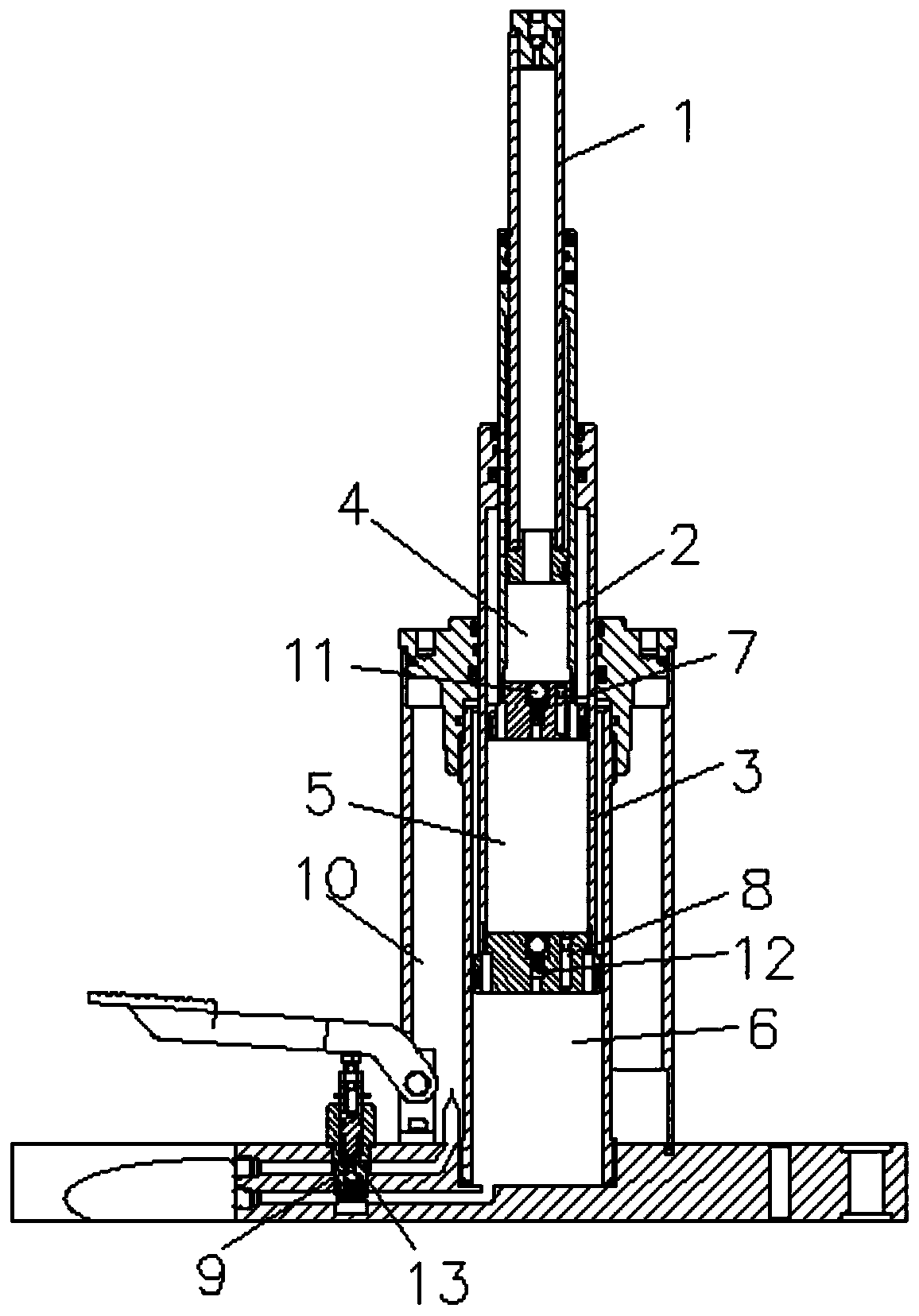
[0072] A vertical jack, comprising an outer casing cavity 10 and an oil cylinder cavity 6, the outer casing cavity 10 and the oil cylinder cavity 6 can be connected through an external oil circuit to realize oil return; the communication between the oil cylinder cavity 6 and the outer casing cavity 10 can adopt any existing technology. In order to realize the technical function of the present application, it is only necessary to ensure that the oil passage can pass through installations such as valve body components and parts with holes, so that the oil passage has small oil drainage holes.

[0073] In order to realize the load-bearing function of the jack, in this embodiment, the large piston rod 3 , the middle piston rod 2 and the small piston rod 1 are sequentially nested in the cylinder cavity 6 . Here, the characteristics of the piston rods of various sizes are: a rod-shaped member with a hollow structure that a normal piston rod has, and a piston head is arranged at one e...

Embodiment 2

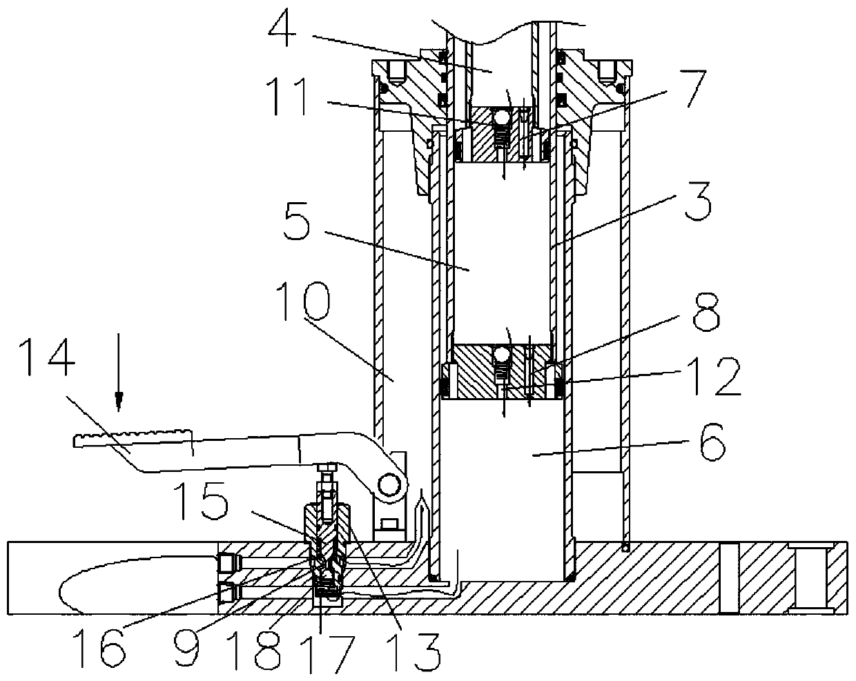
[0084] In order to avoid the failure or instability of the jack, the oil drain hole is designed with a small hole structure to play a similar damping effect, so that the multi-section piston rod can be lowered slowly under load. Simultaneously, in order to realize the uniform rate of descent, this application limits the cross-sectional area of ​​each cavity of the drain hole, defines the cross-sectional area of ​​the drain hole-7 as S1, and the cross-sectional area of ​​the piston rod cavity-4 as S11, S11 and S1 The ratio of A1 is A1; the cross-sectional area of ​​oil drain hole one 7 is defined as S2, the cross-sectional area of ​​piston rod cavity one 4 is S22, and the ratio of S22 and S2 is A2; the cross-sectional area of ​​defined oil drain hole three 9 is S3, and the oil cylinder The cross-sectional area of ​​cavity 6 is S33, and the ratio of S33 to S3 is A3; wherein, A1:A2:A3=1:(1.8-2.1):(3.8-4.2).

[0085] Preferably, A1:A2:A3=1:2:4, so that it is applied to jacks under...

Embodiment 3

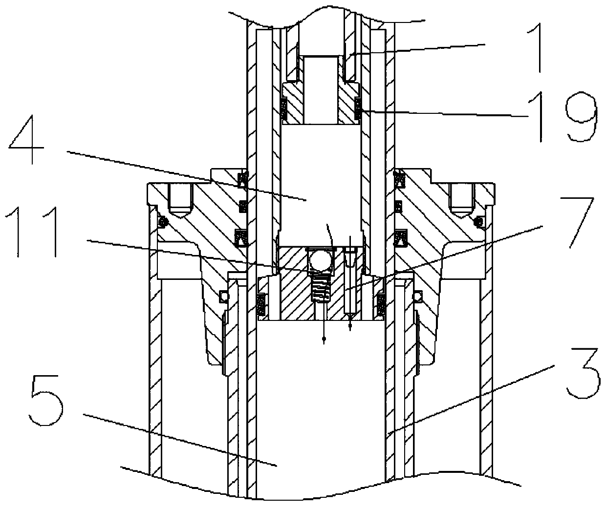
[0088] In order to realize rapid recovery of the piston rods at all levels under no load, the piston head on the middle piston rod 2 is provided with an oil return valve 11; the piston head on the large piston rod 3 is provided with an oil return valve 2 12.

[0089] Such as figure 2 As shown, the oil return valve 11 includes:

[0090] Valve body one, the valve body one has a through-hole combination connecting piston rod chamber one 4 and piston rod chamber two 5; the through-hole combination includes a ball-installation hole and a spring-installation hole coaxially arranged in sequence; wherein, The spring one mounting hole is connected to the piston rod chamber two 5, the ball one mounting hole is connected to the piston rod chamber one 4, and the diameter of the ball one mounting hole is greater than the maximum diameter of the spring one mounting hole;

[0091] Ball 1 is located in the mounting hole of ball 1, and is blocked in the mounting hole of spring 1 under the po...


PUM


Abstract

The invention belongs to the field of jacks, and particularly relates to an oil hydraulic jack. The oil hydraulic jack comprises a first pump, a second pump, an oil cylinder cavity for jack work and an outer sleeve cavity for oil return of the oil cylinder cavity; and the first pump and the second pump are arranged in a linked manner. In the unloading mode of the jack, when the first pump and thesecond pump ascend in a linked manner, a first valve is opened, a second valve is closed, and the outer sleeve cavity communicates with a first cavity; a third valve is opened, a pressure regulating valve is closed, a fourth valve is closed, and the outer sleeve cavity communicates with a second cavity; when the first pump and the second pump descend in a linked mode, the first valve is closed, the second valve is opened, and the first cavity communicates with the oil cylinder cavity; the third valve is opened, the fourth valve is closed, the pressure regulating valve is closed, and the secondcavity communicates with the oil cylinder cavity. In the loading mode of the jack, the first valve is closed, the second valve is closed, the third valve is opened, the fourth valve is closed, the pressure regulating valve is opened, and the oil cylinder cavity communicates with the outer sleeve cavity and the second cavity. The oil hydraulic jack provided by the invention has a novel oil path structure to realize the labor-saving function of quickly lifting the load single pump by the double pumps.

Description

technical field [0001] The invention belongs to the field of jacks, and in particular relates to a vertical jack. Background technique [0002] Vertical jacks are used in various machining industries, maintenance industries, transportation industries, etc. In order to better adapt to the development and application of the industry, vertical jacks have gradually been improved from a single form to a multi-stroke. For example, a vertical three-stroke jack disclosed in Chinese patent CN201530703U includes a cylinder body, a pump body is arranged on one side of the cylinder body, a lifting rod is arranged on the pump body, and an oil circuit A and an oil circuit B are respectively arranged at the lower end of the pump body. The oil cavity at the lower end of the primary piston rod communicates, and the oil passage B communicates with the oil storage chamber. There are oil seals on the first-stage piston rod and the third-stage piston rod respectively; an oil return valve is arr...

Claims


Application Information

Patent Timeline
IPC IPC(8): B66F3/28B66F3/42F15B13/02
CPCB66F3/28B66F3/42F15B13/02
Inventor 唐洁
Owner CHANGSHU TONGRUN AUTO ACCESSORY
Why Eureka
Try Eureka