
Lifting oil cylinder buffer device for fork lift

A technology of lifting oil cylinder and buffer device, applied in the direction of lifting device, fluid pressure actuating device, mechanical equipment, etc., can solve the problems of high noise, large pressure pulse, small sound requirements, etc., to ensure the buffer effect and eliminate the sound. , the effect of eliminating out-of-sync phenomenon

Pending Publication Date: 2020-03-24
HEFEI HAIYUAN MACHINERY
View PDF0 Cites 0 Cited by
  • Summary
  • Abstract
  • Description
  • Claims
  • Application Information

AI Technical Summary

Problems solved by technology

[0004] The purpose of the present invention is to provide a lifting cylinder buffer device for forklifts. In order to overcome the buffer structure between the buffer plunger and the buffer bushing in the above-mentioned industry, the horizontal gap between the two is adjusted to achieve buffer performance. When the piston of the oil cylinder descends to the buffer stage, the throttle is instantaneous, the pressure of the hydraulic oil changes instantaneously, and the pressure pulse is large and produces noise. Ordinary internal combustion forklifts generate relatively large noise, so there is no special requirement for this noise. Requirements, electric forklifts with high noise requirements and forklift trucks with special requirements for working conditions have abnormal noise when the piston descends to the buffer position, and the cylinders on both sides are lowered due to the magnification of processing errors caused by the too small buffer gap of the cylinder. In the end, the asynchronous phenomenon, the buffer structure between the buffer plunger and the buffer bushing in the industry is usually a technical problem of adjusting the horizontal gap between the two to achieve buffer performance.

Method used


Image

  • Lifting oil cylinder buffer device for fork lift
  • Lifting oil cylinder buffer device for fork lift

Examples


Embodiment Construction

[0020] The technical solutions of the present invention will be clearly and completely described below in conjunction with the embodiments. Apparently, the described embodiments are only some of the embodiments of the present invention, not all of them. Based on the embodiments of the present invention, all other embodiments obtained by persons of ordinary skill in the art without creative efforts fall within the protection scope of the present invention.

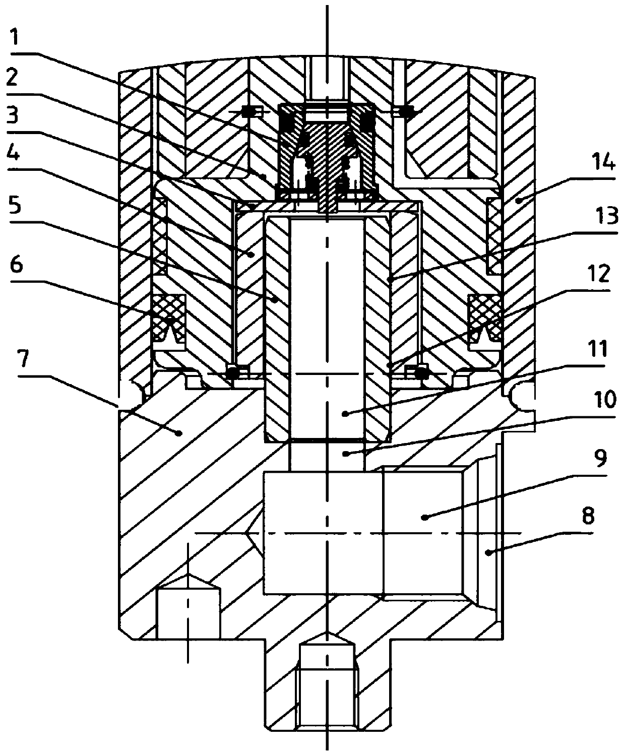
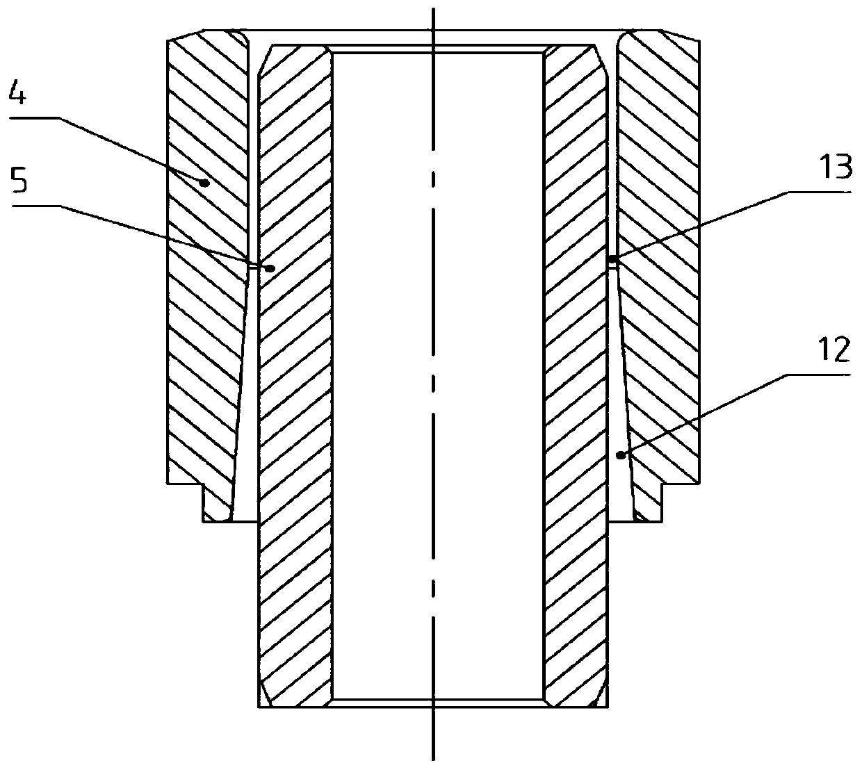
[0021] see Figure 1-2 As shown, a lifting cylinder buffer device for forklifts includes a check valve 1, a piston 2, a gasket 3, a buffer bushing 4, a buffer plunger 5, a cylinder seat 7, an oil inlet 8, a first oil Cavity 9, second oil chamber 10, oil outlet 11 and cylinder barrel 14, a first oil chamber 9 is horizontally opened inside the cylinder base 7, and an oil inlet hole 8 is opened on one side of the cylinder base 7, and the oil inlet hole 8 is connected with the first The oil chamber 9 is conductively connected,...


PUM


Abstract

The invention discloses a lifting oil cylinder buffer device for a fork lift. The lifting oil cylinder buffer device comprises a one-way valve, a piston, a gasket, a buffer shaft sleeve, a buffer plunger, a cylinder base, an oil inlet hole, a first oil cavity, a second oil cavity, an oil outlet and a cylinder barrel. The first oil cavity is horizontally formed in the cylinder base, and the oil inlet hole is formed in one side of the cylinder base. The original buffer shaft sleeve with a straight hole inside is changed into the horn hole and straight hole integrated buffer shaft sleeve so thatafter the buffer plunger enters the buffer shaft sleeve, oil throttling is changed into progressive throttling, the throttling effect is improved in an ascending way slowly and stably, the buffer gapis adjusted to be 16 mm of the optimal size obtained after the test, and thus the buffering effect is guaranteed and the asynchronous phenomenon caused by accumulation of machining errors is eliminated, the noise generated by instantaneous throttling when the oil cylinder of the electric fork lift and the fork lift with special working condition requirements on noise moves to the buffering part iseliminated, and an ideal buffering effect is achieved by adjusting the optimal buffering gap through a large number of on-site tests.

Description

technical field [0001] The invention relates to the field of forklift equipment, in particular to a lifting cylinder buffer device for a forklift. Background technique [0002] At present, two-stage mast forklifts, two-stage full-free mast forklifts, and three-stage full-free mast forklifts are common in the forklift market. The oil return circuit of the hydraulic oil is sealed, and when the load of the cylinder decreases, the load forces the hydraulic oil below the piston to pass through the gap between the buffer plunger and the buffer bushing to play a buffering role. [0003] In the industry, the buffer structure between the buffer plunger and the buffer bushing is usually to adjust the horizontal gap between the two to achieve buffer performance. Therefore, when the cylinder piston descends to the buffer stage, the throttle is instantaneous, the hydraulic oil pressure changes instantaneously, and the pressure pulse is large. However, when there is noise, ordinary inter...

Claims


Application Information

Patent Timeline
IPC IPC(8): B66F9/22F15B15/22
CPCB66F9/22F15B15/222F15B2215/30
Inventor 沈四海
Owner HEFEI HAIYUAN MACHINERY
Learn More