Foundation strengthening method

A foundation reinforcement and foundation technology, applied in foundation structure engineering, construction, sheet pile wall and other directions, can solve the problems of poor resistance to pressure and shear force, inconvenient operation, unstable column, etc. The effect of enhanced diffusion radius to ensure stability

Active Publication Date: 2020-03-24
淮安市建筑设计研究院有限公司
View PDF4 Cites 1 Cited by
  • Summary
  • Abstract
  • Description
  • Claims
  • Application Information

AI Technical Summary

Problems solved by technology

[0002] There is an existing foundation reinforcement technology, such as the patent number "201610488648.7", and the name is "ground reinforcement device and foundation reinforcement method". Concrete can effectively reinforce the foundation; but in the implementation, the positioning of the grouting plate in this technical solution requires the grouting plate to be moved to the corresponding position, and the elastic pin for positioning is inserted into the positioning hole through the traction rope, which is extremely difficult to operate. Inconvenient, first of all, the grouting disc needs an additional position, and if there is interference between the first traction rope and the second traction rope during this process, the elastic pin will pop out in advance, and this error is irreversible; in addition, during the grouting process, The pressure of the high-pressure grout on the elastic pin may make it overcome the elastic force and move the grouting plate; and the original state of the elastic pin relies on the arc baffle to limit the position, and the arc baffle forms a large impact on the grout during the grouting process. resistance and will cause the grout to produce a circulating flow that is not conducive to grouting in the grouting plate, which is not conducive to the outward diffusion of the grout, and it is difficult to produce the so-called cross-linking effect; finally, since the grouting operation is only limited to the outward through the grouting plate Diffusion to achieve the so-called cross-linking effect. There is no slurry in the column of coarse sand accumulation, so that the column as the reinforcement core is not stable. Therefore, even if the local cross-linking effect is strong, the resistance to pressure and shear force still less effective

Method used


Image

  • Foundation strengthening method
  • Foundation strengthening method
  • Foundation strengthening method

Examples


Embodiment Construction

[0017] The present invention will be further described below in conjunction with accompanying drawing of description and embodiment:

[0018] A ground reinforcement method, comprising the steps of:

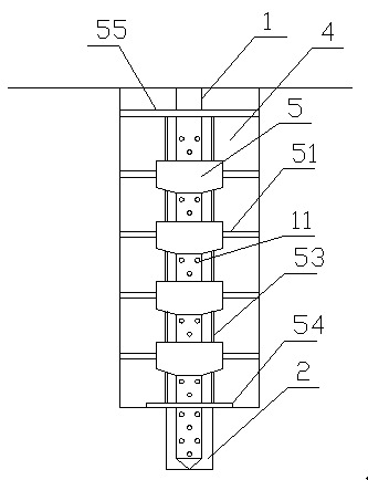
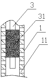
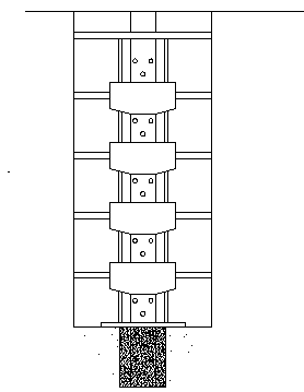
[0019] Such as figure 1 As shown, (1), drill the foundation hole, insert the lower end of the flower tube 1 with several holes 11 evenly distributed on the pipe wall into the foundation hole 2, fill the lower part of the foundation hole with coarse sand and then tamp it; combine figure 2 As shown, (2) Insert the first inner sleeve 3 into the flower tube 1, the lower part of the first inner sleeve has a plugging head 31, the outer diameter of the plugging head is equal to the inner diameter of the flower tube, Inject water glass solution and cement slurry into the bottom of the flower tube through the first inner sleeve, and wait for the bottom end of the flower tube to solidify in the foundation hole; (3) as image 3 As shown, the upper part of the foundation hole is reamed to ...


PUM


Abstract

The invention relates to a foundation strengthening method. The foundation strengthening method comprises the following steps that firstly, foundation hole drilling is conducted, the lower end of a floral tube is inserted in a foundation hole, and the lower section of the foundation hole is filled with coarse sand to be compacted, wherein a plurality of holes are evenly distributed in the tube wall of the floral tube; secondly, a water glass solution and cement paste are injected into the bottom of the floral tube through a first inner casing pipe, and the bottom end of the floral tube is cured in the foundation hole; thirdly, chambering is conducted on the upper portion of the foundation hole, an expanding hole is formed, and then grouting discs sequentially sleeve the part, located at the expanding hole, of the floral tube at equal intervals; fourthly, the expanding hole is filled with coarse sand; fifthly, a second inner casing pipe is used for sequentially pumping the high-pressurewater glass solution into various grouting discs, the water glass solution is outwards scoured and diffused through a grouting pipe, and then the second inner casing pipe is pulled out; and sixthly,the cement paste is injected into the floral tube, part of the cement paste is outwards diffused through the grouting pipe and makes contact with the water glass solution, the other part directly enters the coarse sand in the expanding hole through the holes in the floral tube, and work is finished after cement paste liquid curing.

Description

technical field [0001] The invention relates to a ground reinforcement method. Background technique [0002] There is an existing foundation reinforcement technology, such as the patent number "201610488648.7", and the name is "ground reinforcement device and foundation reinforcement method". Concrete can effectively reinforce the foundation; but in the implementation, the positioning of the grouting plate in this technical solution requires the grouting plate to be moved to the corresponding position, and the elastic pin for positioning is inserted into the positioning hole through the traction rope, which is extremely difficult to operate. Inconvenient, first of all, the grouting disc needs an additional position, and if there is interference between the first traction rope and the second traction rope during this process, the elastic pin will pop out in advance, and this error is irreversible; in addition, during the grouting process, The pressure of the high-pressure gr...

Claims


Application Information

Patent Timeline
Patent Type & Authority Applications(China)
IPC IPC(8): E02D5/36E02D5/62E02D5/48E02D15/04
CPCE02D5/36E02D5/48E02D5/62E02D15/04E02D2250/003E02D2300/0021E02D2300/0025
Inventor 尤文月洪辉孟凡静
Owner 淮安市建筑设计研究院有限公司
Why Eureka
Try Eureka