Hydrological multifunctional carrying platform
A multi-functional, hydrological technology, applied in the field of monitoring equipment and hydrological detection, can solve the problems of poor concealment of transmission mechanism, restriction of load-bearing capacity, short maintenance cycle, etc., to improve safety and reliability, avoid human-made malicious damage, and environmental impact small effect
- Summary
- Abstract
- Description
- Claims
- Application Information
AI Technical Summary
Problems solved by technology
Method used
Image
Examples
Embodiment 1
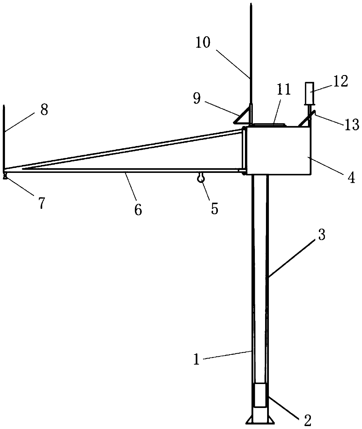
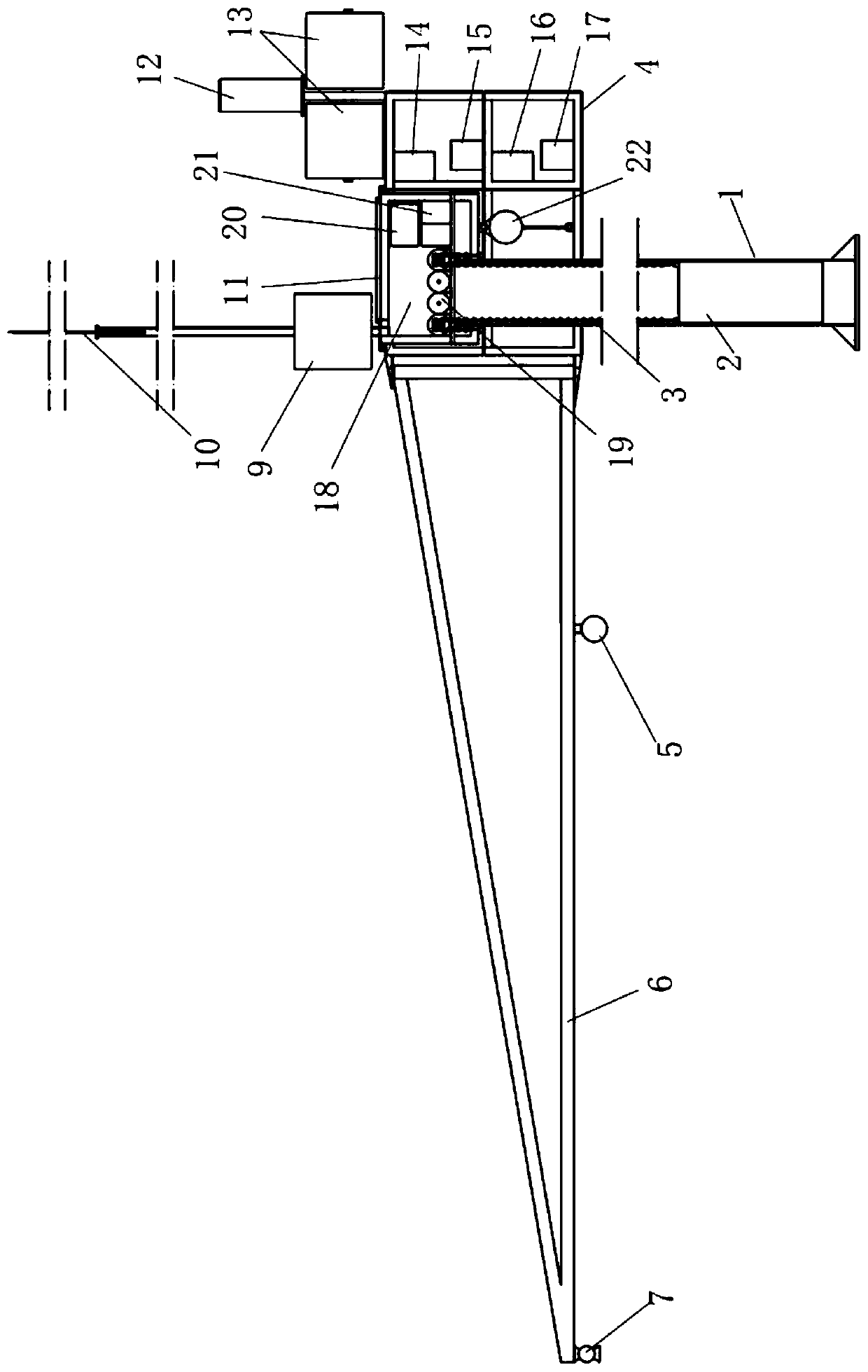
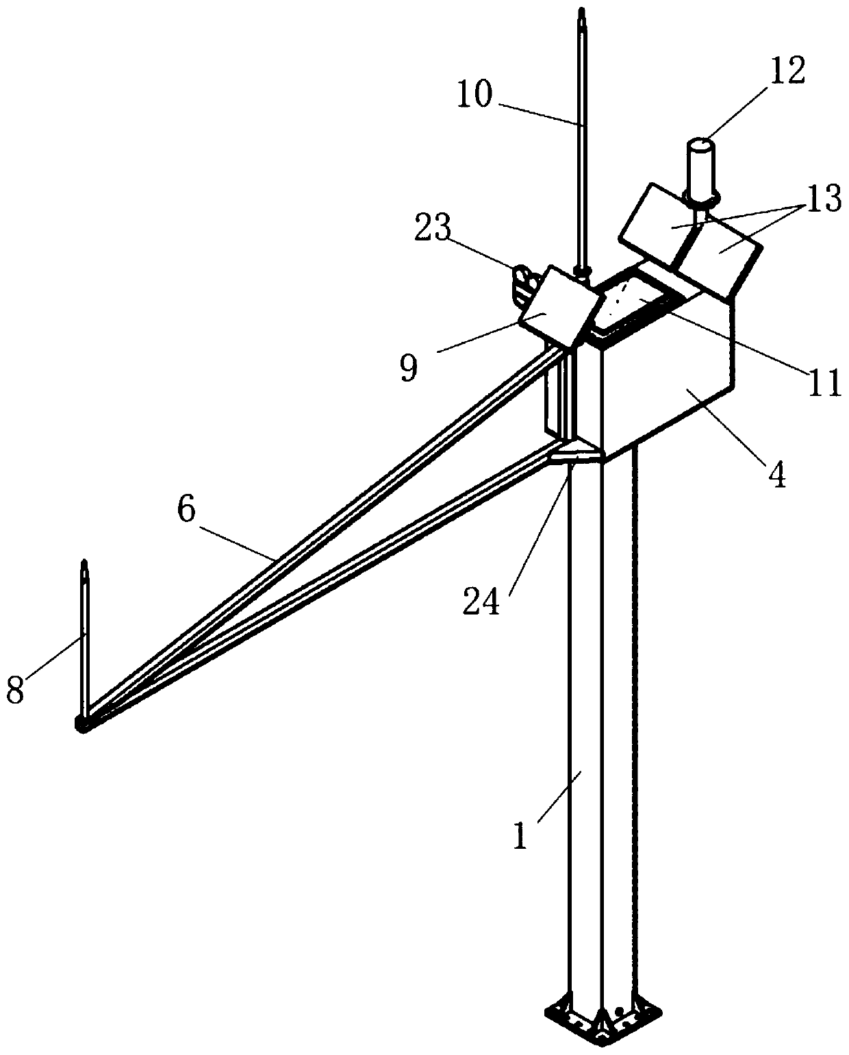
[0042] Such as Figure 1-Figure 10 As shown, the hydrological multifunctional carrying platform includes a main support arm 1 and an elevator cabin 4 set outside the main support arm 1 . The cross-section of the main support arm 1 is rectangular, the structure is stable, and the ability to resist flood impact is strong.
[0043] Wherein, the top of the main support arm 1 is provided with a lifting control box 18, and a pair of supporting shafts 27 arranged in parallel are fixed on the bottom plate 1802 of the lifting control box 18, and sprockets 28 are respectively fixed at both ends of the supporting shaft 27, four Two sprockets 28 are positioned at the four corners of the main support arm 1 in the horizontal direction, and a synchronous transmission mechanism 19 is provided between the two support shafts 27, and the power input end of the synchronous transmission mechanism 19 is connected with the drive motor speed reducer 29. The main support arm 1 is a hollow arm and a c...
Embodiment 2
[0054] Such as Figure 11-Figure 13 As shown, in this embodiment, the hydrological multifunctional platform is used to install the radar flow meter 30 , the remote monitoring camera 5 and the rain gauge 12 .
[0055] The both sides of this hydrological multi-function carrying platform elevator cabin 4 are all provided with horizontal jib 6, the quantity of radar flowmeter 30 is two, is respectively fixed on the cantilever end of two horizontal jibs 6, and the quantity of remote monitoring camera 5 is One, set on one of the horizontal sub-arms 6 to get final product. The remote measurement and control units RTU14, 16 and power supply units 15, 17 corresponding to the radar flowmeter 30 and the remote monitoring camera 5 are arranged in the lift cabin 4.
[0056] The top of the lift control box 18 and the top of the lift cabin 4 are equipped with solar panels, the solar panel 9 on the top of the lift control box 18 is connected with the power supply unit 21 of the electric cont...
Embodiment 3
[0060] Such as Figure 14-Figure 16 As shown, in this embodiment, the hydrological multi-function carrying platform is used to install a bubble water level gauge (omitted due to positional relationship), a remote monitoring camera 5 and a rain gauge 12 .
[0061] There is no horizontal jib outside the elevator cabin 4, and the remote measurement and control units RTU31, 32 and power supply units 33, 34 corresponding to the bubble water level gauge and the remote monitoring camera 5 are fixed in the lifting control box 18, and the gas pipe for the detection of the bubble water level gauge is along the main support. The inner side of the arm 1 extends to its bottom and is led out from the foundation 36. The probe 35 of the bubble level gauge is connected to the end of the air pipe and placed in the water outside the foundation 36. The edge of the lifting control box 18 is provided with a support arm 37 corresponding to the remote monitoring camera 5, and the remote monitoring ca...
PUM
 Abstract
Description
Claims
Application Information
 - R&D
- Intellectual Property
- Life Sciences
- Materials
- Tech Scout
- Unparalleled Data Quality
- Higher Quality Content
- 60% Fewer Hallucinations
Browse by: Latest US Patents, China's latest patents, Technical Efficacy Thesaurus, Application Domain, Technology Topic, Popular Technical Reports.
© 2025 PatSnap. All rights reserved.Legal|Privacy policy|Modern Slavery Act Transparency Statement|Sitemap|About US| Contact US: help@patsnap.com


