Horizontal claw wear resistance testing machine

A wear resistance and testing machine technology, applied in the direction of testing wear resistance, measuring device, strength characteristics, etc., can solve the problems of low operating cost, affecting test results, manufacturing cost, site construction cost and operation and maintenance cost, etc. Isolate external interference, facilitate installation and debugging, and measure the effect of fast and accurate

Active Publication Date: 2020-03-24
SHANGHAI DIANJI UNIV
View PDF8 Cites 0 Cited by
  • Summary
  • Abstract
  • Description
  • Claims
  • Application Information

AI Technical Summary

Problems solved by technology

In order to test the performance of the new claw, there are mainly two types of testing technologies currently used. One is to simulate the real working conditions of the whole set of mechanisms. The test operation cost is very high; the other is to use the test machine to simulate the performance of the hook claw. The simulated test machine occupies a small area and has low operating costs, which can basically simulate the real working conditions.
[0003] Using a whole set of mechanism for real working condition test simulation, its manufacturing cost, site construction cost and operation and maintenance cost are relatively high; the existing simulation test machine, its mechanism is manufactured vertically, which is not convenient for test and observation, and the machine is controlled by crankshaft drive The up and down movement of the rod, due to the counterweight at its lower end, will generate vibration and noise during no-load and running, which will affect the test results and reduce the life of the test mechanism

Method used


Image

  • Horizontal claw wear resistance testing machine
  • Horizontal claw wear resistance testing machine
  • Horizontal claw wear resistance testing machine

Examples


Embodiment

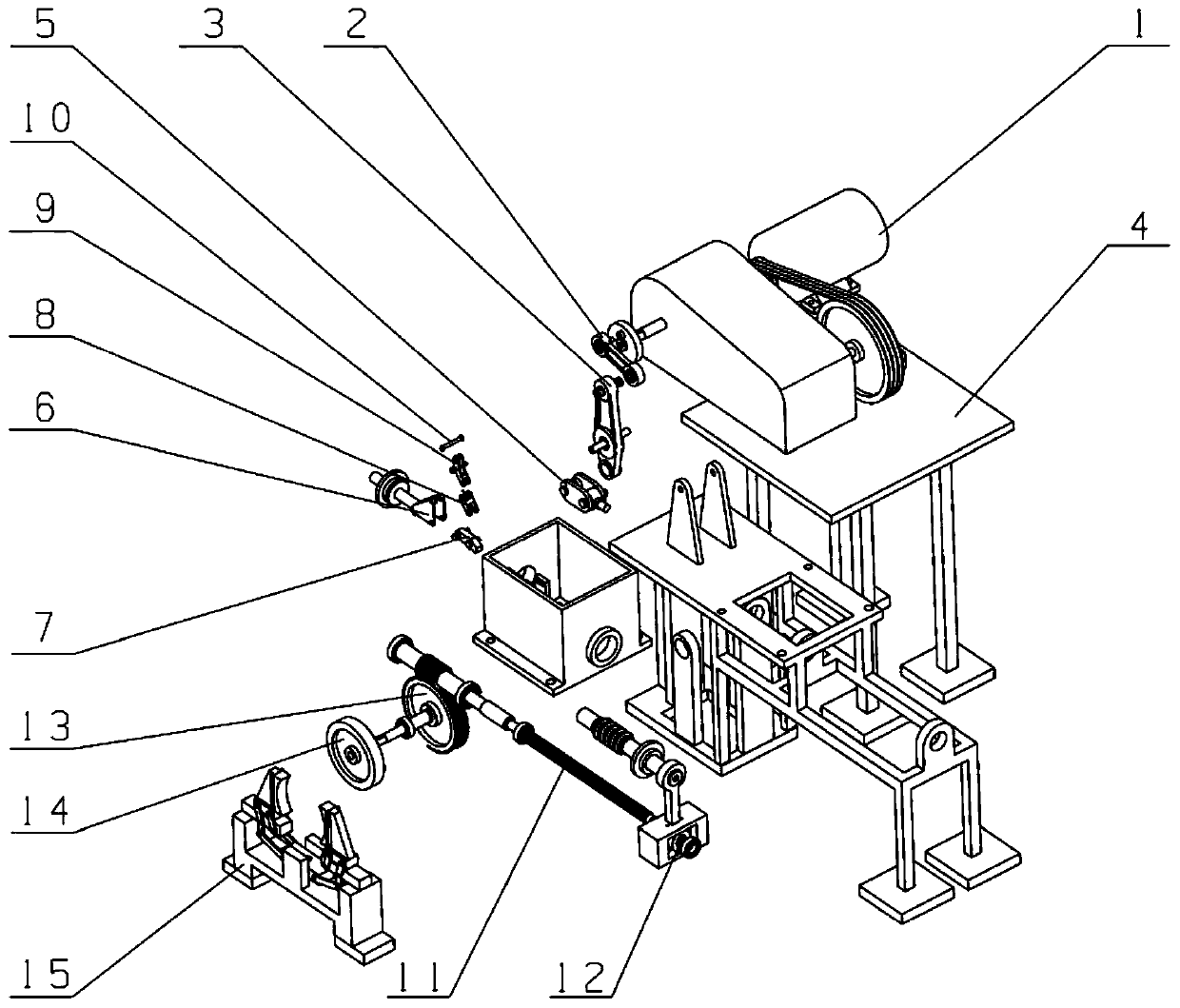
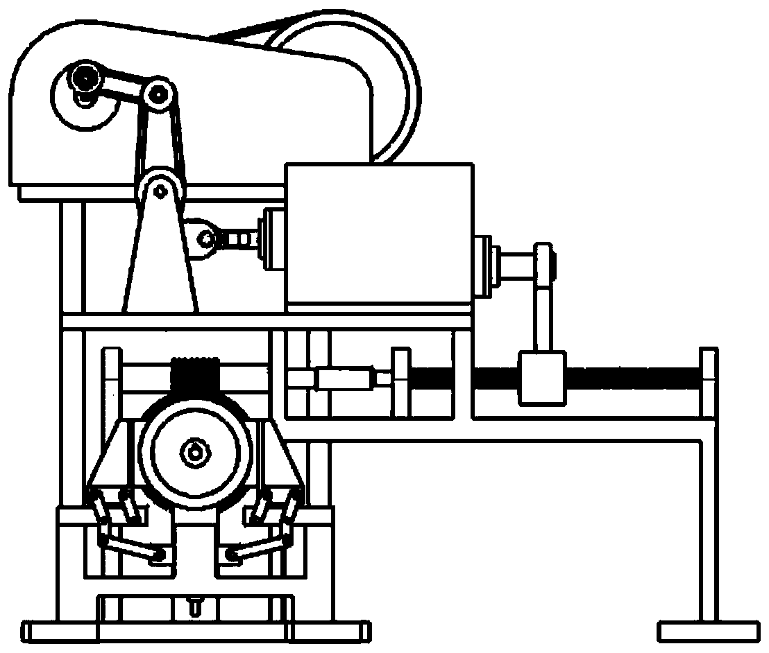
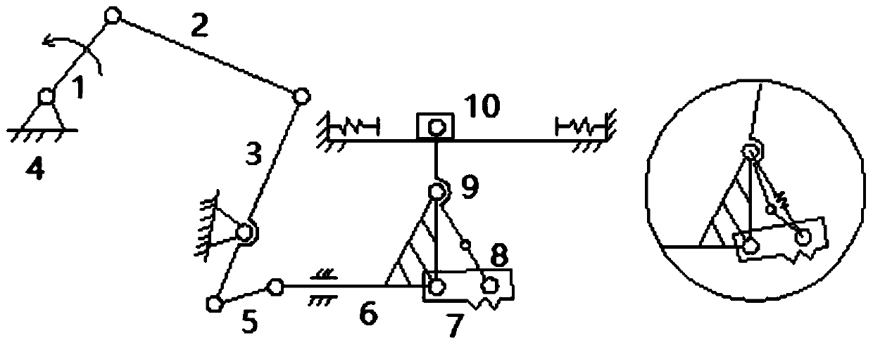
[0035] This embodiment provides a horizontal claw wear resistance testing machine, which includes a driving assembly, a simulation assembly and a loading assembly connected in sequence, the driving assembly includes a crank rocker mechanism connected to the power source 1, and the rocker of the crank rocker mechanism 3 The second lever is formed by the second fulcrum, the power source 1 is connected to the crank-rocker mechanism through a reducer, and the simulation assembly includes a second rod 9 and a first rod 6 connected at one end to the rocker 3 of the crank-rocker mechanism, The other end of the first rod 6 is horizontally connected with one end of the claw 7, one end of the second rod 9 is connected with the other end of the claw 7 and forms an acute angle, and the other end of the second rod 9 is connected with the horizontally slidable slide The sliding part 10 slides on the horizontal track, the end of the horizontal track is provided with a spring, the second rod 9...


PUM


Abstract

The invention relates to a horizontal claw wear resistance testing machine. The machine comprises a driving assembly, a simulation assembly and a loading assembly which are connected in sequence, thesimulation assembly comprises a second rod piece and a first rod piece of which one end is connected with the driving assembly; wherein the other end of the first rod piece is horizontally connected with one end of the claw, one end of the second rod piece is connected with the other end of the claw to form an included angle, the other end of the second rod piece is connected with the sliding piece arranged on the horizontal rail, and the control rod is horizontally connected with the loading assembly. Compared with the prior art, a horizontal type horizontal mechanism is adopted to simulate the up-and-down linear motion of the claw driving control rod; the abrasion resistance test of the claw in two directions can be completed; the sliding part can simulate the process that the claw grabsthe control rod, the overall height size of the horizontal mechanism is controllable, the cost is lower than that of real working condition simulation, the control rod is horizontally placed, the influence of the balance weight of the vertical testing machine is avoided, measurement is rapid and accurate, and installation, debugging, operation and observation are convenient.

Description

technical field [0001] The invention relates to the technical field of instrumentation analysis and measurement control, in particular to a horizontal claw abrasion resistance testing machine. Background technique [0002] The claw is an important core part of the nuclear reaction control drive mechanism. When working, the claw clamps the control rod and makes up and down adjustment movements. Its working environment is in the environment medium of the reactor circuit, and it is repeatedly in the working and neutral state. The design life should reach several hundred million times. In order to test the performance of the new claw, there are mainly two types of testing technologies currently used. One is to simulate the real working conditions of the whole set of mechanisms. The test operation cost is very high; the other is to use a test machine to simulate the performance of the hook claw. The simulation test machine occupies less land and has low operating costs, and can ...

Claims


Application Information

Patent Timeline
Patent Type & Authority Applications(China)
IPC IPC(8): G01N3/56G01N3/02
CPCG01N3/56G01N3/02G01N2203/0005
Inventor 邵兵原恩桃李桐
Owner SHANGHAI DIANJI UNIV
Why Eureka
Try Eureka