
Bridge structure optimization method and system based on vehicle load and intelligent equipment

A vehicle load and bridge structure technology, applied in mechanical equipment, multi-objective optimization, design optimization/simulation, etc., can solve problems such as waste of materials used in bridge components, unreasonable allocation of bridge management and maintenance resources, etc., and achieve optimal bridge stress , Save material consumption, improve the effect of life cycle cost

Pending Publication Date: 2020-03-24
GUANGZHOU UNIVERSITY
View PDF5 Cites 3 Cited by
  • Summary
  • Abstract
  • Description
  • Claims
  • Application Information

AI Technical Summary

Problems solved by technology

[0004] However, the current bridge design adopts a uniform lane vehicle load standard, and the load standards of all lanes are directly related to the road grade. This design idea believes that the load grades of all lanes are consistent with the load grade of the designed road. Differential lane loads will inevitably lead to more prominent vulnerability of bridge components near the heavy lane than those close to the overtaking lane, and once a component is severely damaged or fails, it will trigger the replacement or reinforcement of the entire bridge
Therefore, the current uniform lane vehicle load standard in bridge design will waste the material consumption of many bridge components, resulting in unreasonable allocation of bridge management and maintenance resources in operation

Method used


Image

  • Bridge structure optimization method and system based on vehicle load and intelligent equipment
  • Bridge structure optimization method and system based on vehicle load and intelligent equipment
  • Bridge structure optimization method and system based on vehicle load and intelligent equipment

Examples


Embodiment Construction

[0053] In order to make the purposes, technical solutions and advantages of the embodiments of the present invention clearer, the technical solutions in the embodiments of the present invention will be clearly and completely described below with reference to the accompanying drawings in the embodiments of the present invention. Obviously, the described embodiments These are some embodiments of the present invention, but not all embodiments. Based on the embodiments of the present invention, all other embodiments obtained by those of ordinary skill in the art without creative efforts shall fall within the protection scope of the present invention.

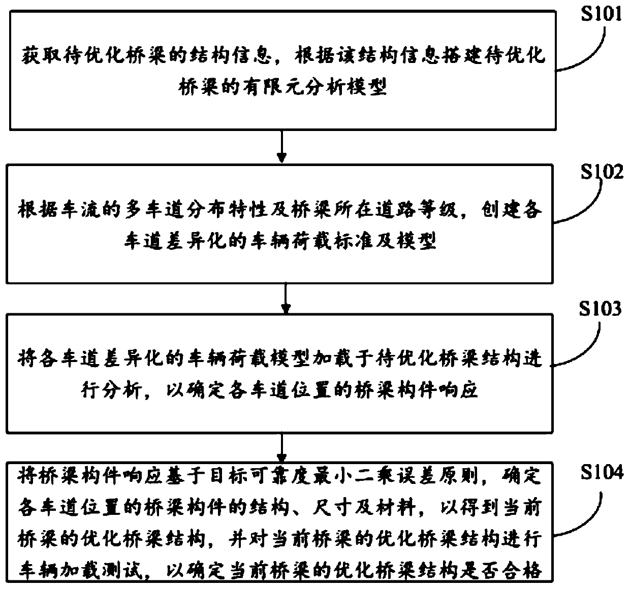
[0054] see figure 1 , a bridge structure optimization method based on vehicle load proposed in the first embodiment of the present invention, which includes steps S101 to S104:

[0055] In step S101, structural information of the bridge to be optimized is acquired, and a finite element analysis model of the bridge to be optimized i...


PUM


Abstract

The invention discloses a bridge structure optimization method and system based on vehicle load and intelligent equipment. The bridge structure optimization method comprises the steps: obtaining the structure information of a to-be-optimized bridge, and building a finite element analysis model of the to-be-optimized bridge according to the structure information; according to the multi-lane distribution characteristics of the traffic flow and the road grade of the bridge, creating differentiated vehicle load standards and models of all lanes; loading the differentiated vehicle load model of each lane to a to-be-optimized bridge structure for analysis so as to determine bridge member response of each lane position; and determining the structure, the size and the material of the bridge memberat each lane position based on a target reliability least square error principle according to the bridge member response so as to obtain an optimized bridge structure of the current bridge, and carrying out a vehicle loading test on the optimized bridge structure of the current bridge. According to the bridge structure optimization method, the bridge components at all lane positions can have consistent reliability under the action of different lane loads, and the actual application requirements are met.

Description

technical field [0001] The invention relates to the technical field of bridge engineering, in particular to a vehicle load-based bridge structure optimization method, system and intelligent equipment. Background technique [0002] In recent years, with the vigorous growth of my country's road transportation industry, the previously built roads and bridges can no longer meet the current transportation needs, and urgently need to be widened and rebuilt to meet the needs of multi-lane traffic. In order to meet the growing traffic demand, new road projects are often designed with multi-lane structures. Therefore, multi-lane road and bridge structures have become an important feature of current traffic infrastructure construction. [0003] The actual traffic flow contains various vehicle types and characteristics, but can be generally divided into two categories: passenger cars and trucks. Due to the characteristics of vehicle shape and load characteristics, passenger cars often...

Claims


Application Information

Patent Timeline
IPC IPC(8): G06F30/13G06F30/23G06F111/06
CPCY02T10/40
Inventor 周军勇张灵恺郑焱龙
Owner GUANGZHOU UNIVERSITY
Learn More