Antenna adjustment method and device and computer storage medium

An adjustment device and adjustment method technology, applied in the field of communication, can solve the problems of increasing cost, unfavorable overall solution layout, increasing antenna isolation, etc.

Active Publication Date: 2020-03-24
ZTE CORP
View PDF17 Cites 5 Cited by
  • Summary
  • Abstract
  • Description
  • Claims
  • Application Information

AI Technical Summary

Problems solved by technology

However, the existing solutions have the following defects: firstly, the selection of radio frequency devices with better linearity will increase the cost, and may also cause the decline of other indicators; secondly, increasing the isolation between antennas will increase the antenna’s The difficulty of debugging and the layout that is not conducive to the overall solution may also degrade the performance of the antenna

Method used


Image

  • Antenna adjustment method and device and computer storage medium
  • Antenna adjustment method and device and computer storage medium
  • Antenna adjustment method and device and computer storage medium

Examples


Embodiment 1

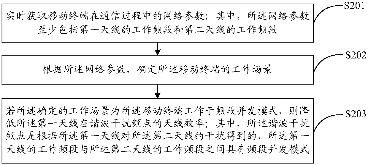
[0054] See figure 2 , Which shows an antenna adjustment method provided by an embodiment of the present invention, which is applied to a mobile terminal including at least a first antenna and a second antenna, and the method may include:

[0055] S201: Acquire network parameters of the mobile terminal in the communication process in real time; wherein, the network parameters include at least the working frequency band of the first antenna and the working frequency band of the second antenna;

[0056] S202: Determine the working scenario of the mobile terminal according to the network parameters;

[0057] S203: If the determined working scenario is that the mobile terminal works in the frequency band concurrent mode, reduce the antenna efficiency of the first antenna at the harmonic interference frequency; wherein, the harmonic interference frequency is based on the The interference of the first antenna to the second antenna is obtained, and there is a frequency band concurrent mode ...

Embodiment 2

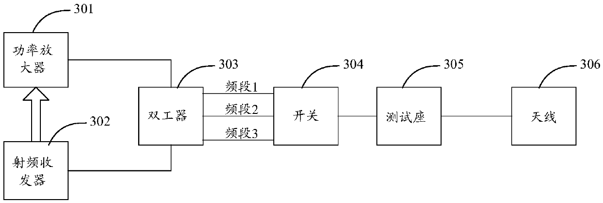
[0084] See image 3 , Which shows a schematic structural diagram of a conventional radio frequency circuit of a mobile terminal according to an embodiment of the present invention; image 3 As shown, the conventional radio frequency circuit 300 includes a power amplifier 301, a radio frequency transceiver 302, a duplexer 303, a switch 304, a test base 305, and an antenna 306; based on the conventional radio frequency circuit 300, the radio frequency signal transmission and communication of a mobile terminal can be realized. Receiving; in the use of mobile terminals, when radio frequency signals of multiple frequency bands are concurrent, in order to solve the problem that harmonic signals cannot be suppressed when the radio frequency signals are concurrent due to the common antenna of multiple frequency bands, which causes the antenna sensitivity to decrease, In the embodiment of the present invention, an adjustable unit can be added to the radio frequency circuit; see Figure 4 ...

Embodiment 3

[0095] It is assumed that the embodiment of the present invention mainly involves four frequency bands: frequency band A, frequency band B, frequency band C, and frequency band X; among them, the specific description of frequency band A, frequency band B, frequency band C, and frequency band X is as follows:

[0096] (1) Band A and Band C share the first antenna, and Band B has a separate second antenna;

[0097] (2) Band A and Band B have concurrent use scenarios;

[0098] (3) Non-linear high-order harmonics of frequency band A (second harmonic, third harmonic, etc.) or other frequency band X intermodulation frequency is the same or similar to the frequency of frequency band B (the frequency difference is less than 10MHz), which will interfere with frequency band B work;

[0099] (4) Band A and Band C share the first antenna and are not supported at the same time. The frequency of frequency band C is similar to that of frequency band B (the frequency difference is less than 10MHz), ...


PUM


Abstract

The embodiment of the invention discloses an antenna adjustment method and device and a computer storage medium, the method is applied to a mobile terminal at least comprising a first antenna and a second antenna, and network parameters of the mobile terminal in a communication process are acquired in real time; wherein the network parameters at least comprise a working frequency band of a first antenna and a working frequency band of a second antenna; a working scene of the mobile terminal is determined according to the network parameters; if the determined working scene is that the mobile terminal works in a frequency band concurrent mode, the antenna efficiency of the first antenna at a harmonic interference frequency point is reduced, wherein the harmonic interference frequency point is obtained according to the interference of the first antenna to the second antenna, and a frequency band concurrent mode exists between the working frequency band of the first antenna and the workingfrequency band of the second antenna; therefore, the problem of signal interference caused by a frequency band concurrent mode can be effectively solved, and meanwhile, the antenna performance is also improved.

Description

Technical field [0001] The present invention relates to the field of communication technology, and in particular to an antenna adjustment method, device and computer storage medium. Background technique [0002] With the rapid development of mobile communication technology, the communication frequency bands supported by mobile phones and other terminals continue to increase, which greatly increases the difficulty of terminal antenna design. It is difficult to achieve high antenna efficiency and high isolation for all communication frequency bands supported by the terminal. Especially when there are concurrent scenarios in the radio frequency signals of two communication frequency bands and the harmonic frequency of one frequency band is in the frequency band of the other frequency band, the signal interference is caused. [0003] At present, the above problems have become more prominent. The existing solutions are to reduce harmonic energy by selecting switches and other radio freq...

Claims


Application Information

Patent Timeline
Patent Type & Authority Applications(China)
IPC IPC(8): H01Q1/24H01Q1/52H01Q5/10H01Q5/28H01Q5/307H04B1/04H04B1/12H04B1/18
CPCH01Q1/242H01Q1/521H01Q5/10H01Q5/28H01Q5/307H04B1/0475H04B1/12H04B1/18H01Q1/24H04B1/04H01Q1/52
Inventor 陈明清
Owner ZTE CORP
Why Eureka
Try Eureka