Eureka AIR delivers breakthrough ideas for toughest innovation challenges, trusted by R&D personnel around the world.

An assembly head having mutually engaged rotors

A technology for assembling heads and rotors, applied in the direction of electrical components, electrical components, etc., can solve the problems of assembly machine speed and precision assembly head quality limitations

Active Publication Date: 2020-03-24
ASM ASSEMBLY SYST GMBH & CO
View PDF10 Cites 0 Cited by
  • Summary
  • Abstract
  • Description
  • Claims
  • Application Information

AI Technical Summary

Problems solved by technology

The speed and precision of the assembly machine are therefore limited especially by the mass of the individual assembly heads

Method used


Image

  • An assembly head having mutually engaged rotors
  • An assembly head having mutually engaged rotors
  • An assembly head having mutually engaged rotors

Examples


Embodiment Construction

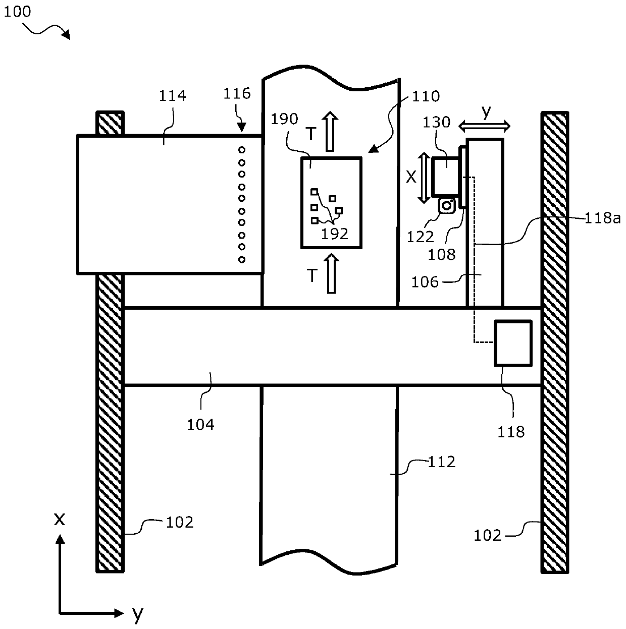
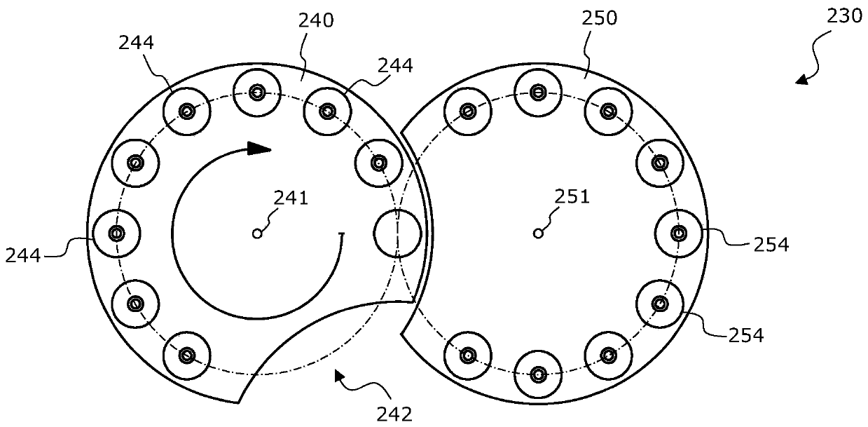
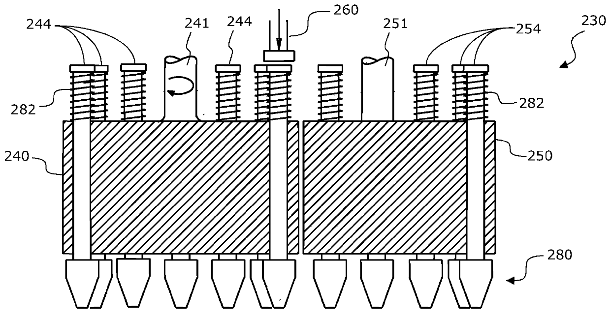
[0082] It should be noted that in the following detailed description, features or components of different embodiments (which are the same or at least functionally identical to corresponding features or components of other embodiments) are marked with the same reference numerals or different reference numerals, and these different The reference numerals of are identical in the last two letters to the reference numerals of identical or at least functionally identical features or components. In order to avoid unnecessary repetition, features or components which have already been explained with reference to the exemplary embodiments described above will not be explained in more detail below.

[0083] Furthermore, it should be pointed out that the embodiments described below represent only a limited selection of possible variants of the invention. In particular, it is possible to combine features of the individual embodiments with one another in a suitable manner, so that many diff...


PUM


Abstract

An assembly head for assembling a component carrier with an electronic component is described. The assembly head comprises: (a) a frame; (b) a first rotor rotatably supported relative to the frame about a first axis of rotation, wherein the first rotor has a plurality of first sleeves each displaceably supported on the first rotor along a longitudinal axis thereof and further configured such thatelement retaining means are each attachable to one end of a respective sleeve; and (c) a second rotor rotatably mounted relative to the frame about a second axis of rotation. The first rotor has a first recess and the second rotor has a second recess; the two recesses are designed and arranged in such a way that the second rotor is freely rotatable in a predetermined angular position of the firstrotor; at a predetermined angular position of the second rotor, the first rotor is free to rotate. An assembly machine having such an assembly head and a method for assembling the component carrier with the electronic component using such an assembly head are also described.

Description

technical field [0001] The present invention generally relates to the technical field of assembly technology. In particular, the present invention relates to a mounting head that can be used to pick up a plurality of electronic components from a component supply system, transfer them to a mounting area of ​​a mounting machine, and place them on a component carrier. In addition, the invention also relates to an assembly machine with such an assembly head and a method for assembling component carriers and electronic components using this assembly head. Background technique [0002] The manufacture of electronic components includes, inter alia, the assembly of component carriers and electronic components. This process is usually done in an assembly machine, where an assembly head picks up components from a component supply system and transfers the picked components to an assembly area where the component carriers to be assembled are located. In the assembly area, the conveyed...

Claims


Application Information

Patent Timeline
Patent Type & Authority Applications(China)
IPC IPC(8): H05K13/04
CPCH05K13/0409H05K13/041H05K13/0411
Inventor 菲利普·威特米斯
Owner ASM ASSEMBLY SYST GMBH & CO
Why Eureka
Eureka Blog
Learn More