Fuel injection device for internal combustion engine

A technology of fuel injection device and internal combustion engine, which is applied in the directions of fuel injection device, fuel injection device with oil accumulator, charging system, etc., can solve complex and expensive problems and achieve the effect of low price

Inactive Publication Date: 2003-05-21
ROBERT BOSCH GMBH
View PDF2 Cites 0 Cited by
  • Summary
  • Abstract
  • Description
  • Claims
  • Application Information

AI Technical Summary

Problems solved by technology

[0003] The disadvantage of this known injection device is that for each nozzle a complex and relatively expensive 3 / 2-way valve is required for the dosing of the additive and a further 3 / 2-way valve is also required for controlling the diesel injection quantity

Method used


Image

  • Fuel injection device for internal combustion engine
  • Fuel injection device for internal combustion engine
  • Fuel injection device for internal combustion engine

Examples


Embodiment Construction

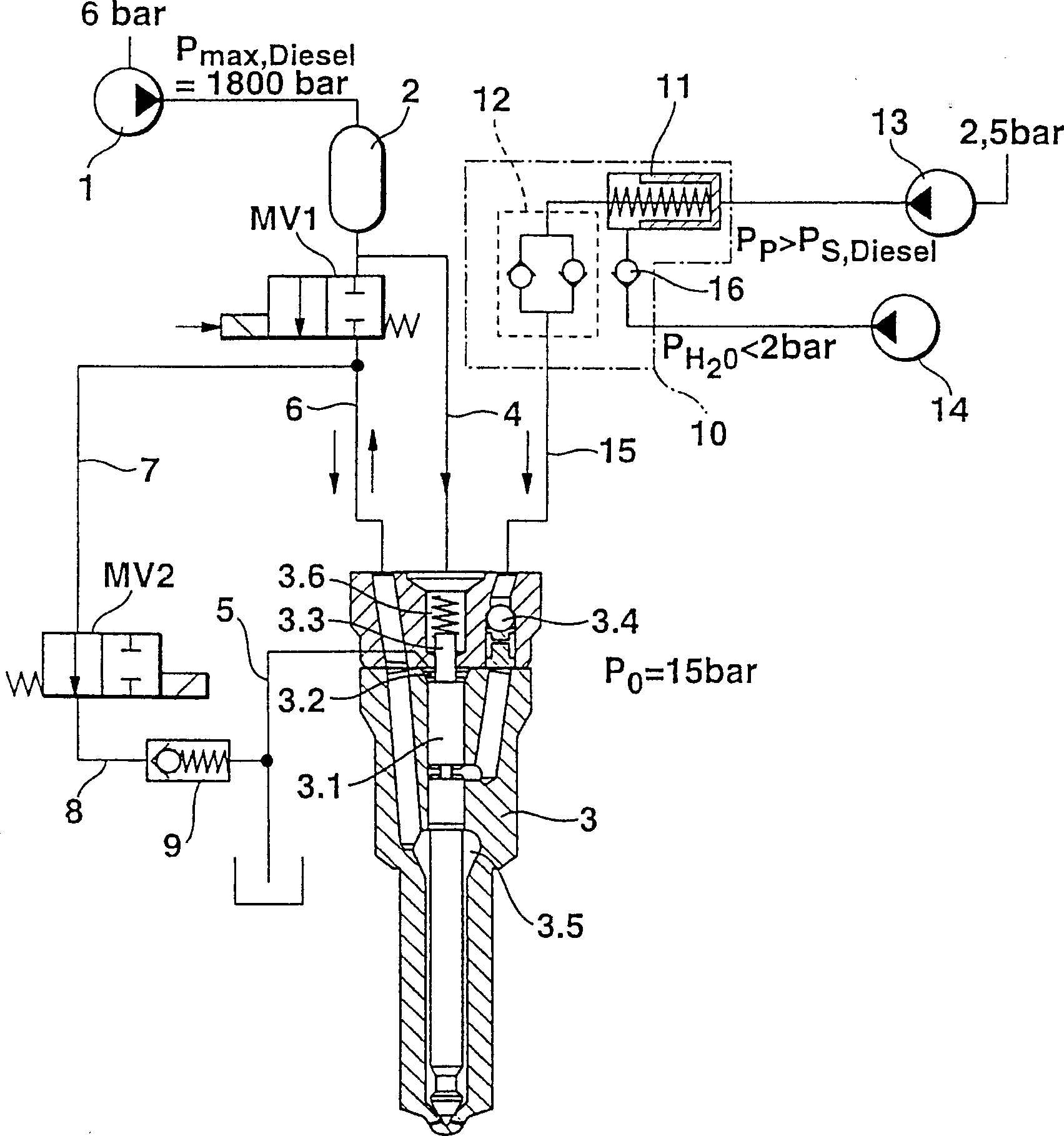
[0023] exist figure 1 A first embodiment of a fuel injection device for an internal combustion engine according to the invention is shown in the table for the injection of two liquids, namely fuel (usually diesel) and an additive fluid (usually water), wherein a high-pressure The pump 1 supplies a common rail pressure accumulator (Common-Rail-Druckspeicher) 2 with fuel at a pressure value of about 1800 bar. Between the common rail pressure accumulator 2 and a pressure chamber 3.5 fed by it via a fuel injection line 6, a quantitative component must then be provided, wherein the pressure chamber 3.5 surrounds the fuel injection needle 3.1 of a two-material nozzle 3, Because the conventional jet pump in the past will be replaced by the combination of the common rail pressure accumulator 2 and the simple pressure pump 1, and the pressure of the accumulator pipe should have a certain value continuously. This task is performed by the first 2 / 2-way valve MV1 in the device according ...


PUM


Abstract

The invention relates to a fuel injection system provided with a Common Rail (2) pressure accumulator filled at high pressure and with a multifuel nozzle (3) for bifluid injection of fuel and an adjunctive liquid into an internal combustion engine. The inventive injection system comprises a first 2 / 2-way valve (MV1) in the injection pipe (6) between the Common Rail pressure accumulator (2) and a pressure chamber (3.5) surrounding the injector pin of the multifuel nozzle, as well as a second 2 / 2-way valve (MV2), the inlet of which is connected via a supply pipe (7) to the injection line (6) at a point located between the first 2 / 2-way valve (MV1) and the pressure chamber (3.5), and the outlet of which is connected via a discharge line (8) to the low pressure side of fuel. It is thus possible to replace the usual valves, technicaly much more expensive, i.e. the magnetically operated 3 / 2-way valves, by 2 / 2-way valves, which are more economical. The invention also enables the adjunctive liquid dosage to be transferred to a regulating valve which operates a whole series of injectors.

Description

technical field [0001] The invention relates to a fuel injection device for an internal combustion engine. Background technique [0002] A fuel injection device of this type is known, for example, from DE4337048. In this case, on the one hand, a dual-substance nozzle is provided for stratified injection of fuel and an additive fluid, such as diesel and water, in order to avoid the impact of harmful substances on the internal combustion engine and, if necessary, to increase the efficiency. On the other hand, so-called "common-rail technology" (Common-Rail-Technik) is also implemented in known fuel injection devices, in which all nozzles for internal combustion engines are fed with fuel under high pressure in a common rail pressure accumulator. [0003] The disadvantage of this known fuel injection device is that a complex and relatively expensive 3 / 2-way valve is required for each nozzle for the dosing of the addition liquid, and another 3 / 2-way valve is required to control ...

Claims


Application Information

Patent Timeline
Patent Type & Authority Patents(China)
IPC IPC(8): F02M43/00F02M43/02F02M43/04F02M47/00F02M47/02F02M63/00
CPCF02M47/027F02M43/00F02M43/04F02M43/02F02M2200/40
Inventor 曼弗雷德·劳夫霍斯特·哈恩道夫
Owner ROBERT BOSCH GMBH
Why Eureka
Try Eureka